
Image compressing method and image compressing apparatus

a compression method and compression apparatus technology, applied in the direction of electrical apparatus, instruments, computing, etc., can solve the problems of conspicuous noise between the two blocks, and achieve the effect of shortening the time necessary for compression, and facilitating compression image generation

Inactive Publication Date: 2008-10-30
SEIKO EPSON CORP
View PDF7 Cites 38 Cited by
  • Summary
  • Abstract
  • Description
  • Claims
  • Application Information

AI Technical Summary

Benefits of technology

[0009]Accordingly, it is possible to easily generate a compression image in which occurrence of block noise is suppressed, while shortening a time necessary for compression.
[0010]A function for converting the value of the color difference signal into the correction value by the correction value converting step may output a maximum value if the absolute value of the color difference signal of the pixel is the maximum value, which can be taken with respect to the color difference signal, and output zero if the absolute value of the color difference signal of the pixel is the same value as the first threshold. Accordingly, it is possible to easily generate a compression image in which occurrence of block noise is suppressed.
[0011]The determining step may further include determining whether the absolute values of the color difference signals of the pixels of the color image are equal to or greater than a second threshold greater than the first threshold, and the correction value converting step may include extracting a pixel, in which the absolute value of one color difference signal is equal to or greater than the second threshold, from the block and outputting the value of the color difference signal of the extracted pixel without conversion, on the basis of the determined result of the determining step. Accordingly, it is possible to easily generate a compression image in which occurrence of block noise is suppressed while shortening a time necessary for compression and generate a compression image in which an original image color is maintained.

Problems solved by technology

Accordingly, in the case where compression is performed for each block, if a block including a large amount of pixels in which the two color difference signal values are in the threshold value and other block are adjacent to each other, block noise between the both blocks is conspicuous.

Method used


Image

  • Image compressing method and image compressing apparatus
  • Image compressing method and image compressing apparatus
  • Image compressing method and image compressing apparatus

Examples


embodiment 1

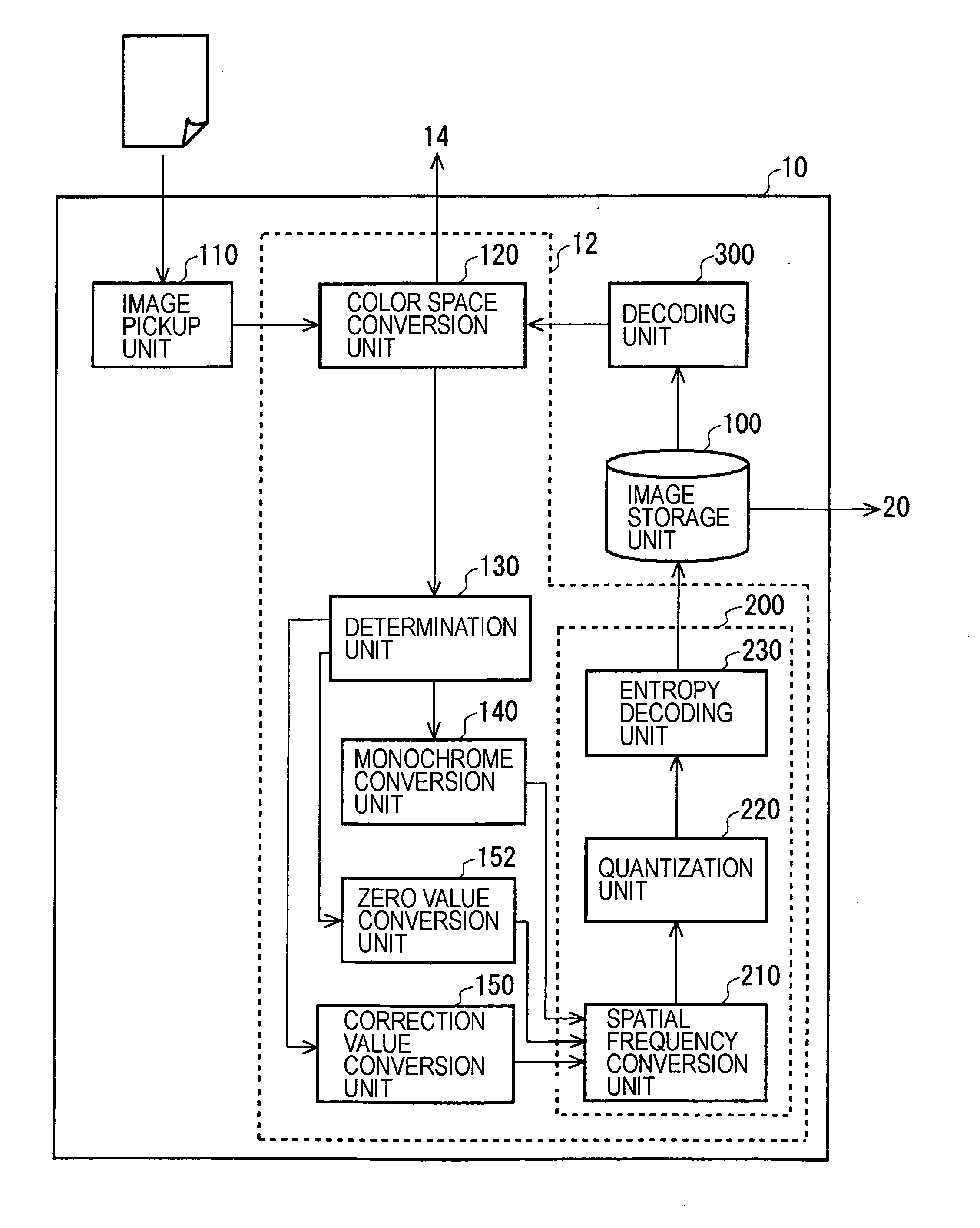
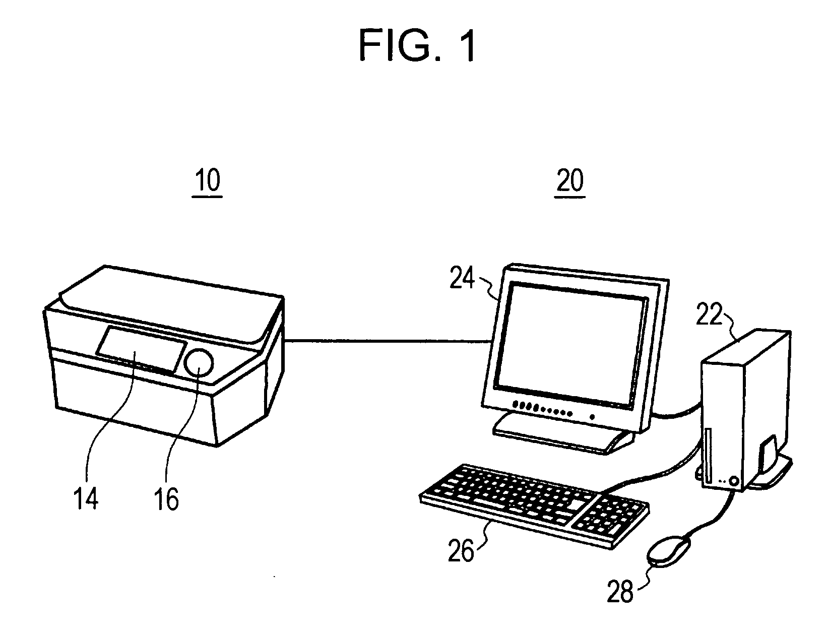
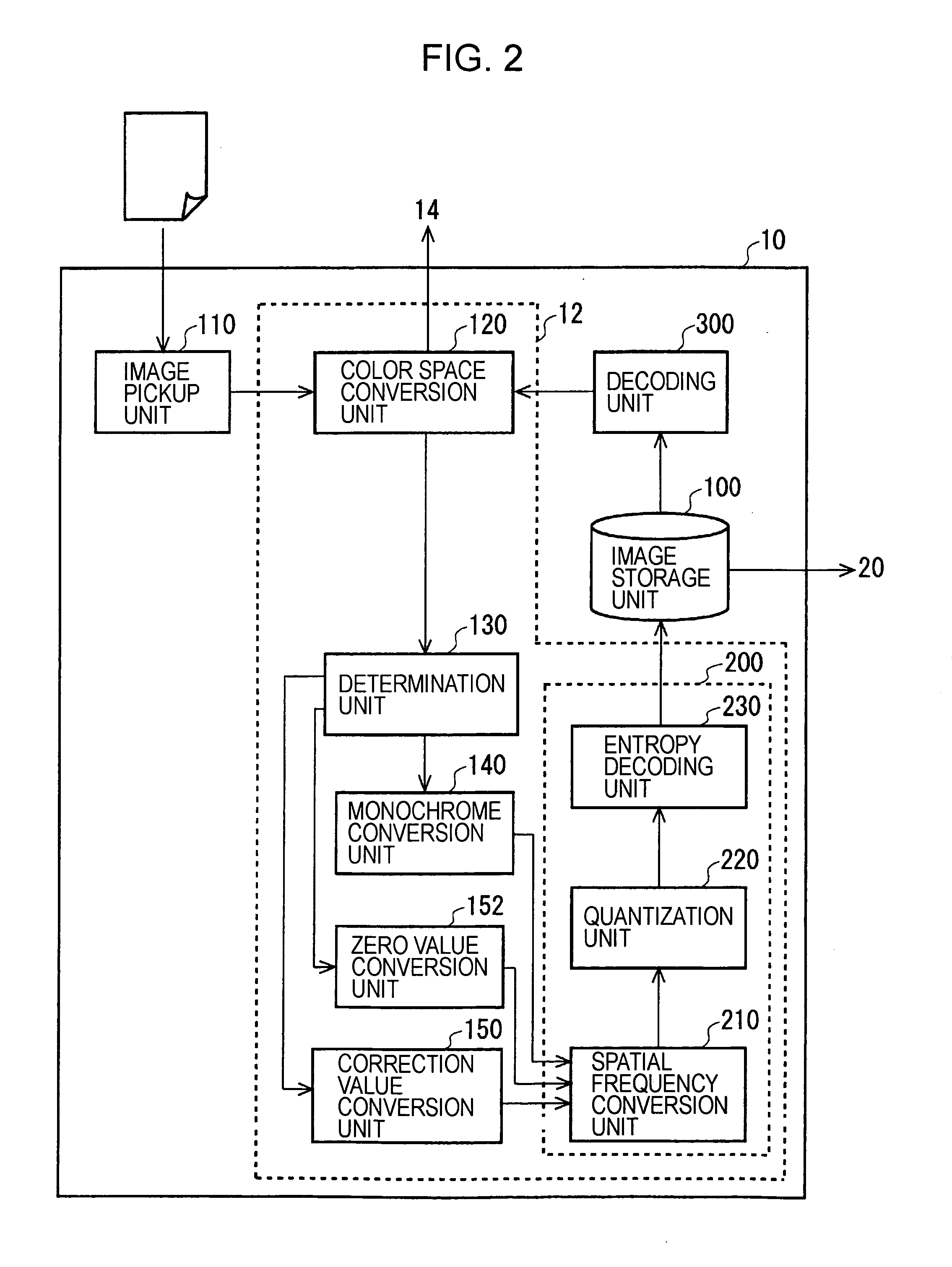
[0027]FIG. 1 is a view showing a scanner 10. The scanner 10 is an example of an image compressing apparatus and includes an operation panel 16 which is an example of input means from a user and a liquid crystal monitor 14 which is an example of output means to the user. This scanner 10 may be a multifunctional machine including a printer function. The scanner 10 receives an instruction of the user via the operation panel 16 and picks up a picture or a photograph using an image pickup device such as a charge coupled device (CCD) for generating a color image. The scanner 10 the color image such as the picked-up picture and photograph to the user via a liquid crystal monitor 14. The scanner 10 outputs the color image to a personal computer 20. The personal computer 20 includes a main body 22, and a display 24 for displaying the image to the user on the basis of the output from the main body 22, and a keyboard26 and a mouse 28 which are examples of the input means from the user to the m...


PUM


Abstract

An image compressing method of dividing and compressing a color image, in which each of pixels is represented by a brightness signal and two color difference signals, into a plurality of blocks including a plurality of pixels, the image compressing method including a compressing step of compressing the color image including the block in which the color difference signal is converted by at least one of a monochrome converting step, a zero value converting step or a correction value converting step.

Description

[0001]The entire disclosure of Japanese Patent Application No. 2007-101053, filed Apr. 6, 2007 is expressly incorporated by reference herein.BACKGROUND[0002]1. Technical Field[0003]The present invention relates to an image compressing method and an image compressing apparatus.[0004]2. Related Art[0005]An image data compressing / encoding apparatus for fixing a color difference component of image data to a predetermined value if a monochrome processing mode is selected and compressing and encoding the fixed color difference component and a brightness component by a compressing / encoding unit is known (for example, see Patent Document 1).[0006][Patent Document 1] Japanese Unexamined Patent Application Publication No. 10-271530[0007]The image data compressing / encoding apparatus disclosed in Patent Document 1 converts two color difference signal values of a substantially monochrome pixel, in which the two color difference signal values are all equal to or less than a threshold value close ...

Claims


Application Information

Patent Timeline
Patent Type & Authority Applications(United States)
IPC IPC(8): G06K9/36H04N1/41H04N19/00H04N19/102H04N19/136H04N19/176H04N19/186H04N19/196H04N19/625H04N19/85H04N19/86H04N19/91
CPCH04N19/176H04N19/186H04N19/137H04N19/124
Inventor SHIMURA, ATSUSHI
Owner SEIKO EPSON CORP
Learn More