Split Mold Insert for a Molding System

a molding system and insert technology, applied in the field of molding systems, can solve the problems of increasing the cost of operating the molding system, premature fatigue, and inability to easily form the neck region by using the cavity and core halves, so as to reduce the amount of material required, reduce the wear of various components, and reduce molding

Inactive Publication Date: 2008-10-30
HUSKY INJECTION MOLDING SYST LTD
View PDF13 Cites 22 Cited by
  • Summary
  • Abstract
  • Description
  • Claims
  • Application Information

AI Technical Summary

Benefits of technology

[0016]A technical effect, amongst others, of the aspects of the present invention may include reduced molding insert stack height. Another technical effect of some of the aspects of the present invention, is a shorter core assembly required, resulting in savings in material required to produce the core assembly. Yet another technical effect of some aspects of the present invention is a potential reduction in wear of various components of the molding insert stack due to improved force distribution. Yet another technical effect of some aspects of the present invention is more efficient cooling due to a particular arrangement of the split mold inserts and the associated slides. It should be expressly understood that not all of the technical effects, in their entirety, need be realized in each and every embodiments of the present invention.

Problems solved by technology

As is appreciated in the art, the neck region can not be easily formed by using the cavity and core halves.
This pre-loading of the top projecting portion of the neck ring and the corresponding female receptacle can lead to premature fatigue and contributes to increased costs of operating the molding system due to a need to replace neck rings more often.
The increased stack height H1 results in several disadvantages associated with the molding insert stack assembly 60.
The increased length of the core insert 61 can lead to several problems, including increased potential for so-called “core shift” of the core insert 61.

Method used


Image

  • Split Mold Insert for a Molding System
  • Split Mold Insert for a Molding System
  • Split Mold Insert for a Molding System

Examples


Embodiment Construction

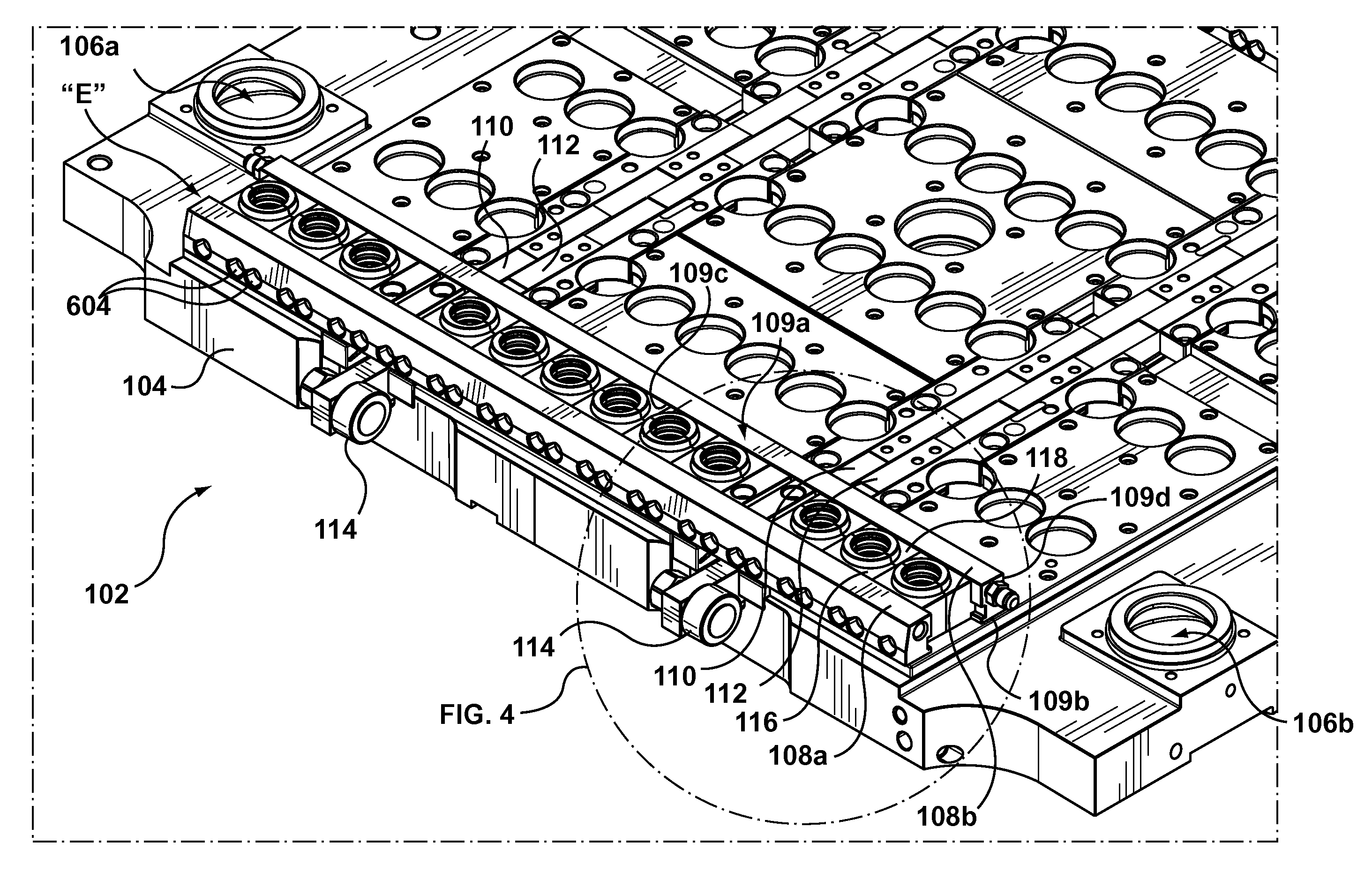
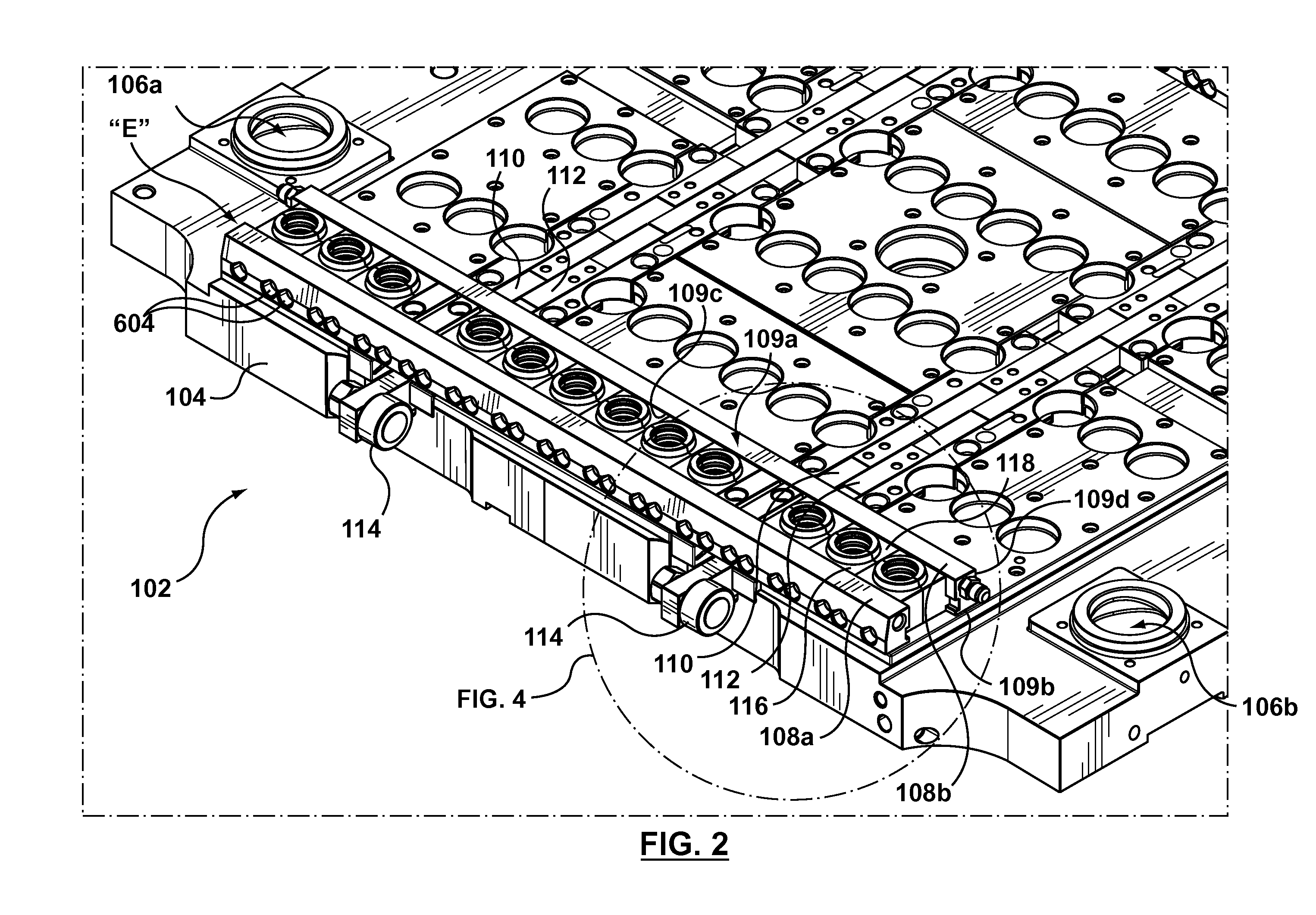
[0029]With reference to FIG. 2, a stripper assembly 102 according to a non-limiting embodiment of the present invention is depicted. The stripper assembly 102 is capable of being configured to implement a split mold insert according to various embodiments of the present invention. The stripper assembly 102 can be used within an injection molding system (not depicted), which can be, for example, an injection molding system for producing a preform, capable of being subsequently blow-molded into a container, such as a beverage container and the like. An example of such a preform is shown in FIG. 3, which depicts a non-limiting embodiment of a preform 302. The preform 302 generally comprises three regions—a neck region 304, an end region 306 disposed at an opposite extreme of the preform 302 and a body region 308 extending between the end region 306 and the neck region 304. The neck region 304 includes, without limitation and as an example only, a thread portion 304a and a support ledge...


PUM

PropertyMeasurementUnit
shapeaaaaaaaaaa
areaaaaaaaaaaa
pressureaaaaaaaaaa

Abstract

According to embodiments of the present invention, there is provided a split mold insert for a molding system. A first split mold insert complementary to a second split mold insert, the first and second split mold inserts configured, in use, to form a neck region of a preform capable of being blow-molded. The first split mold insert comprises a top portion and a bottom portion; the top portion for abutting, in use, a cavity plate assembly and the bottom portion being at an opposite extreme relative to the top portion; a back portion and a face portion opposite each other, extending between the top and bottom portions, the face portion defining a molding surface defining portion for forming, in use, at least a portion of the neck region of the preform; the back portion comprising a connecting interface for connecting, in use, to a slide bar.

Description

FIELD OF THE INVENTION[0001]The present invention generally relates to, but is not limited to, molding systems, and more specifically the present invention relates to, but is not limited to, a split mold insert for use in a molding system.BACKGROUND OF THE INVENTION[0002]Molding is a process by virtue of which a molded article can be formed from molding material by using a molding system. Various molded articles can be formed by using the molding process, such as an injection molding process. One example of a molded article that can be formed, for example, from polyethelene terephalate (PET) material is a preform that is capable of being subsequently blown into a beverage container, such as, a bottle and the like.[0003]As an illustration, injection molding of PET material involves heating the PET material (ex. PET pellets, PEN powder, PLA, etc.) to a homogeneous molten state and injecting, under pressure, the so-melted PET material is injected into a molding cavity defined, at least...

Claims


Application Information

Patent Timeline
Patent Type & Authority Applications(United States)
IPC IPC(8): B29C49/42
CPCB29B2911/1402B29B2911/14026B29B2911/14033B29B2911/1404B29B2911/14106B29B2911/14133B29C45/2618B29C45/332B29C49/06B29K2105/253B29K2105/258Y10S425/058Y10S425/005B29C2949/3024B29C2949/26B29C2949/28B29C2949/24B29C2949/22B29C2949/3032B29C2049/023B29C2949/0715B29C45/26B29C45/72
Inventor KMOCH, SVENFISCH, RALF WALTERMAI, ARNOLDSCHMITZ, FRIEDHELM
Owner HUSKY INJECTION MOLDING SYST LTD
Why Eureka
Try Eureka