Fully shielded backshell for electrical connector

Active Publication Date: 2008-10-30
AEROJET ROCKETDYNE OF DE
View PDF21 Cites 0 Cited by
  • Summary
  • Abstract
  • Description
  • Claims
  • Application Information

AI Technical Summary

Benefits of technology

[0007]A disclosed example connector assembly includes a connector mounted within a backshell and a biasing member that forces the connector into contact with a surface of the backshell to improve ground shield junction performance.
[0008]The example connector assembly includes a connector mounted within the backshell. A shield is attached to the backshell and secured in place by a strap. The shield surrounds wires and other electrical conduits against undesired electromechanical and radio frequency signals that could interfere with desired electrical communication. The example biasing member extends into an internal space defined by the backshell and exerts a biasing force to reduce resistance between the connector and the backshell. The reduced resistance provided by the biasing member improves ground shield junction performance against electromechanical interference (EMI) and radio frequency interference (RFI).
[0009]Accordingly, the example connector assembly provides the desired EMI and RFI shielding by generating a large surface area of contact at a desired pressure with biasing members mounted within the backshell. The positive force provides uniform and dependable EMI-RFI shielding performance.

Problems solved by technology

Outside interference is present in many forms dependent on the environment in which the electrical conductor is installed.
Typical mounting of the connector into the backshell does not provide the desired low resistance.

Method used


Image

  • Fully shielded backshell for electrical connector
  • Fully shielded backshell for electrical connector

Examples


Embodiment Construction

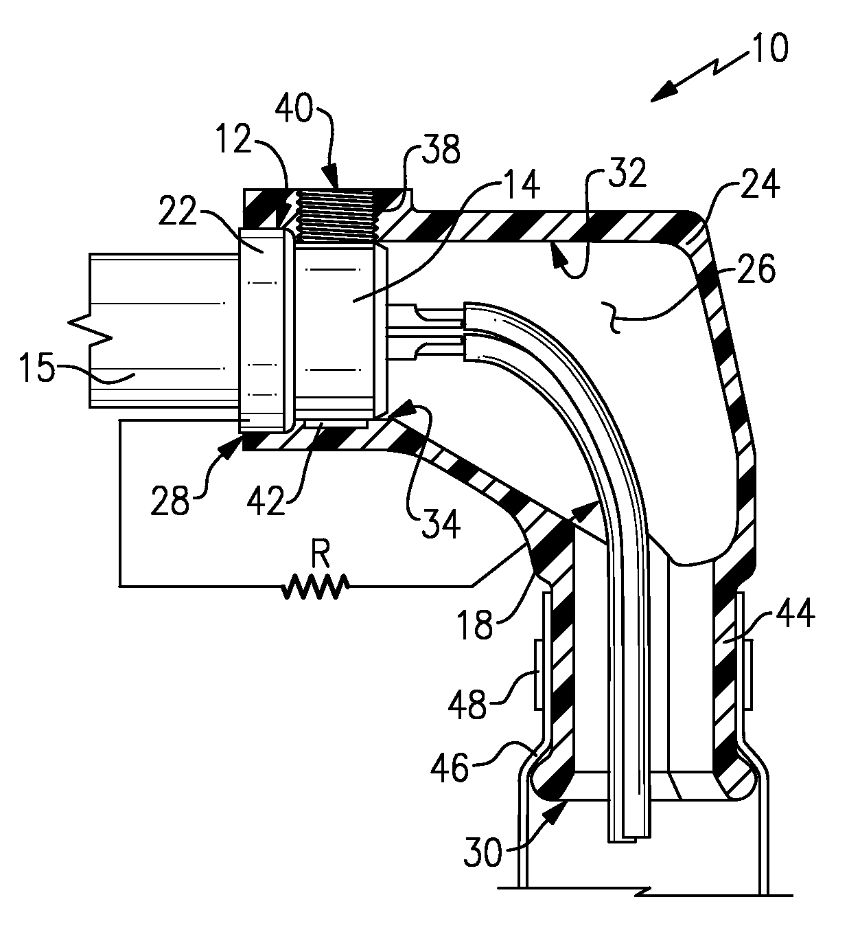
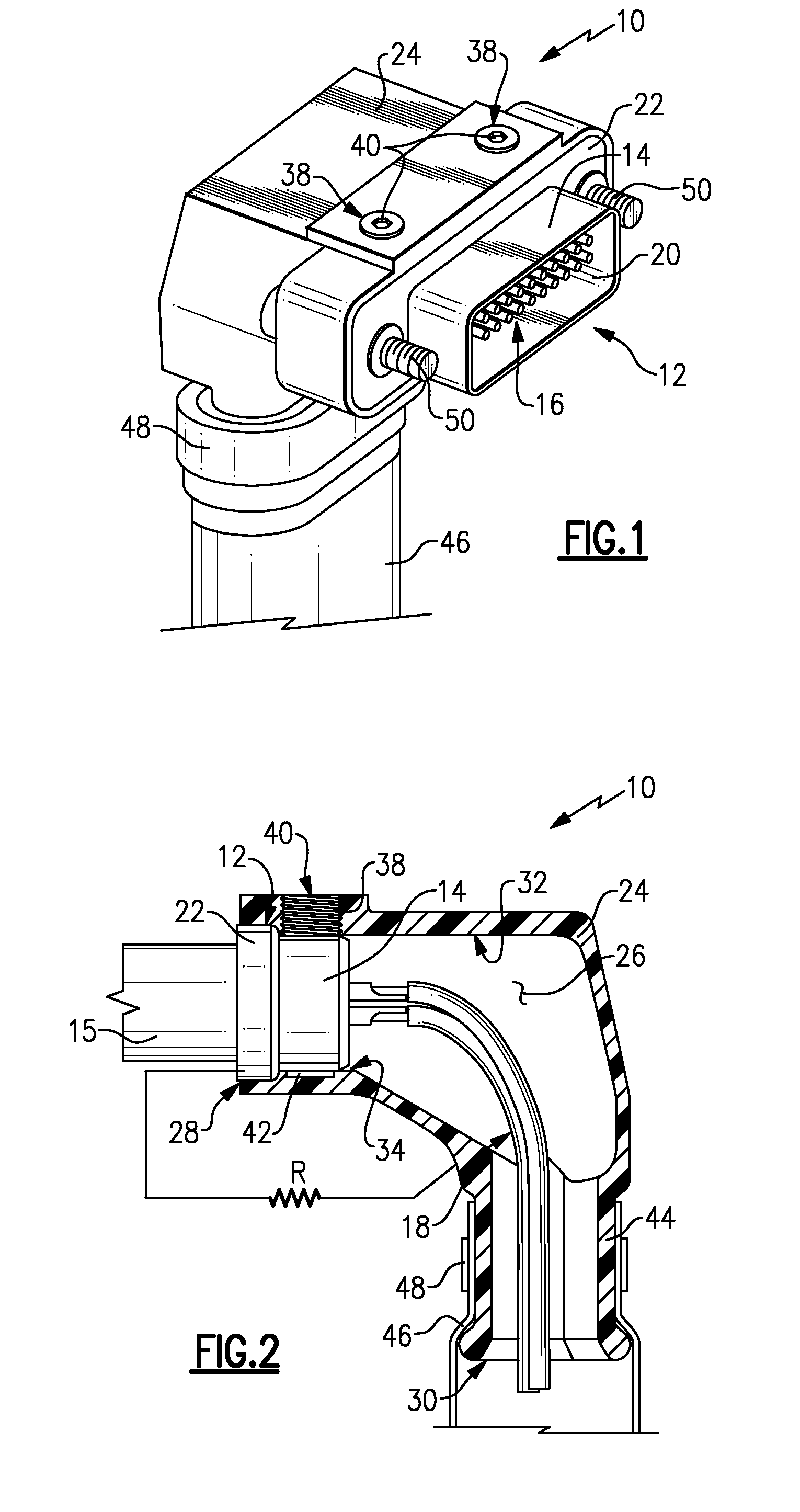
[0013]Referring to FIG. 1, an example connector assembly 10 includes an electrical connector 12 mounted within a backshell 24. The connector 12 includes a plurality of pins 16 for mating with a mating electrical connector 15 (FIG. 2) either on another cable or mounted within a housing. The pins 16 are disposed within a D-shaped mating opening 20 that protects and aligns the pins 16 with a mating electrical connector.

[0014]The connector 12 includes a flange 22 that seats against a front opening 28 (FIG. 2) of the backshell 24. The backshell 24 also includes fasteners 50 for securely mounting the connector assembly 10. A shield 46 is attached to the backshell 24 and secured in place by a strap 48. The shield 46 surrounds wires and other electrical conduits disposed within against undesired electromechanical and radio frequency signals that could interfere with desired electrical communication.

[0015]The backshell 24 includes threaded fasteners 40 that are received within threaded openi...


PUM


Abstract

A connector assembly includes a connector mounted within a backshell and a biasing member that forces the connector into contact with a surface of the backshell to improve ground shield junction performance. The biasing member extends into an internal space defined by the backshell and exerts a biasing force to reduce resistance between the connector and the backshell. The reduced resistance provided by the biasing member improves ground shield junction performance against electromechanical interference (EMI) and radio frequency interference (RFI).

Description

[0001]This invention was made with government support under Contract No.: N00024-03-C-6111 awarded by the Department of the Navy. The government therefore may have certain rights in this invention.BACKGROUND OF THE INVENTION[0002]This invention generally relates to an electrical connector including shielding against interfering electrical signals. More particularly, this invention relates to a backshell providing improved continuity and shielding for an electrical connector.[0003]An electrical connector is a device for providing a secure electrical connection between electrical devices and controllers. In many applications, the connector transmits electrical communications that are utilized to control or relay information. In such applications it is desirable to prevent outside interference from disrupting the electrical communication. Outside interference is present in many forms dependent on the environment in which the electrical conductor is installed.[0004]In many applications ...

Claims


Application Information

Patent Timeline
IPC IPC(8): H01R9/03
CPCH01R13/512H01R13/6592
Inventor GLAAB, GEORGE HENRYNOBLE, RODNEY
Owner AEROJET ROCKETDYNE OF DE
Why Eureka
Try Eureka