
CAPACITIVE MICROMACHINED ULTRASONIC TRANSDUCER (cMUT) DEVICE AND METHOD OF CONTROLLING THE SAME

a micro-machined ultrasonic transducer and micro-machined technology, applied in the direction of mechanical vibration separation, instruments, catheters, etc., can solve the problems of deterioration in spatial resolution and s/n ratio

Active Publication Date: 2008-10-30
OLYMPUS CORP
View PDF16 Cites 52 Cited by
  • Summary
  • Abstract
  • Description
  • Claims
  • Application Information

AI Technical Summary

Benefits of technology

[0036]a superposition unit that is provided on the semiconductor substrate and that is for superposing the driving signal on the DC high-voltage signal;
[0037]a second switching unit that is provided on the semiconductor substrate and that controls the driving signal or the DC high-voltage signal, which is input into the superposition unit; and

Problems solved by technology

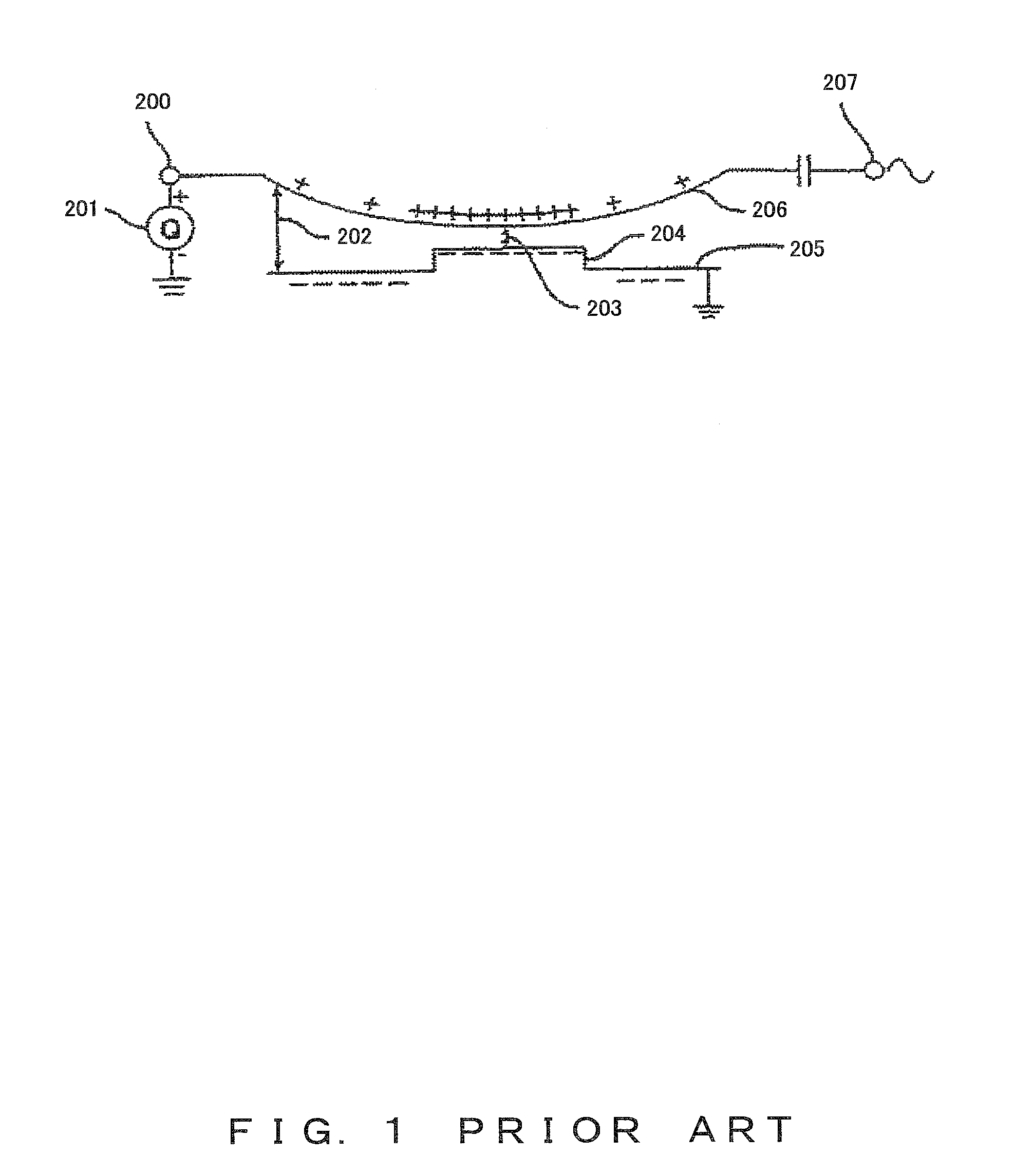
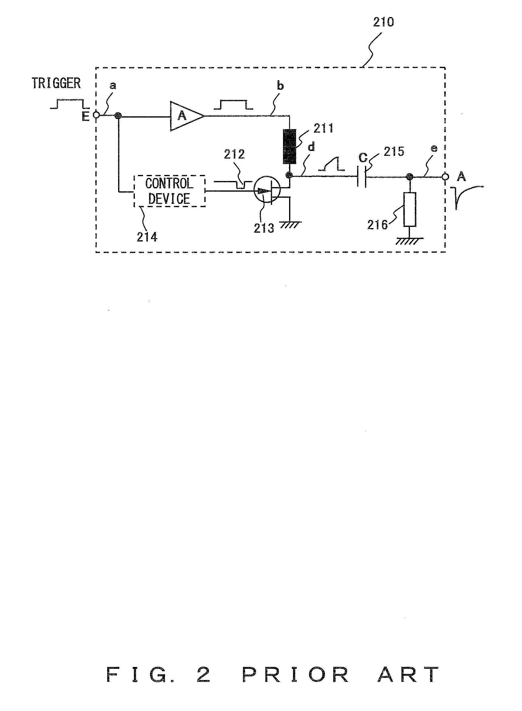
This ringing signal is applied to the piezoelectric transducer without being reduced or blocked, which causes deterioration in the spatial resolution and the S / N ratio.

Method used


Image

  • CAPACITIVE MICROMACHINED ULTRASONIC TRANSDUCER (cMUT) DEVICE AND METHOD OF CONTROLLING THE SAME
  • CAPACITIVE MICROMACHINED ULTRASONIC TRANSDUCER (cMUT) DEVICE AND METHOD OF CONTROLLING THE SAME
  • CAPACITIVE MICROMACHINED ULTRASONIC TRANSDUCER (cMUT) DEVICE AND METHOD OF CONTROLLING THE SAME

Examples


Embodiment Construction

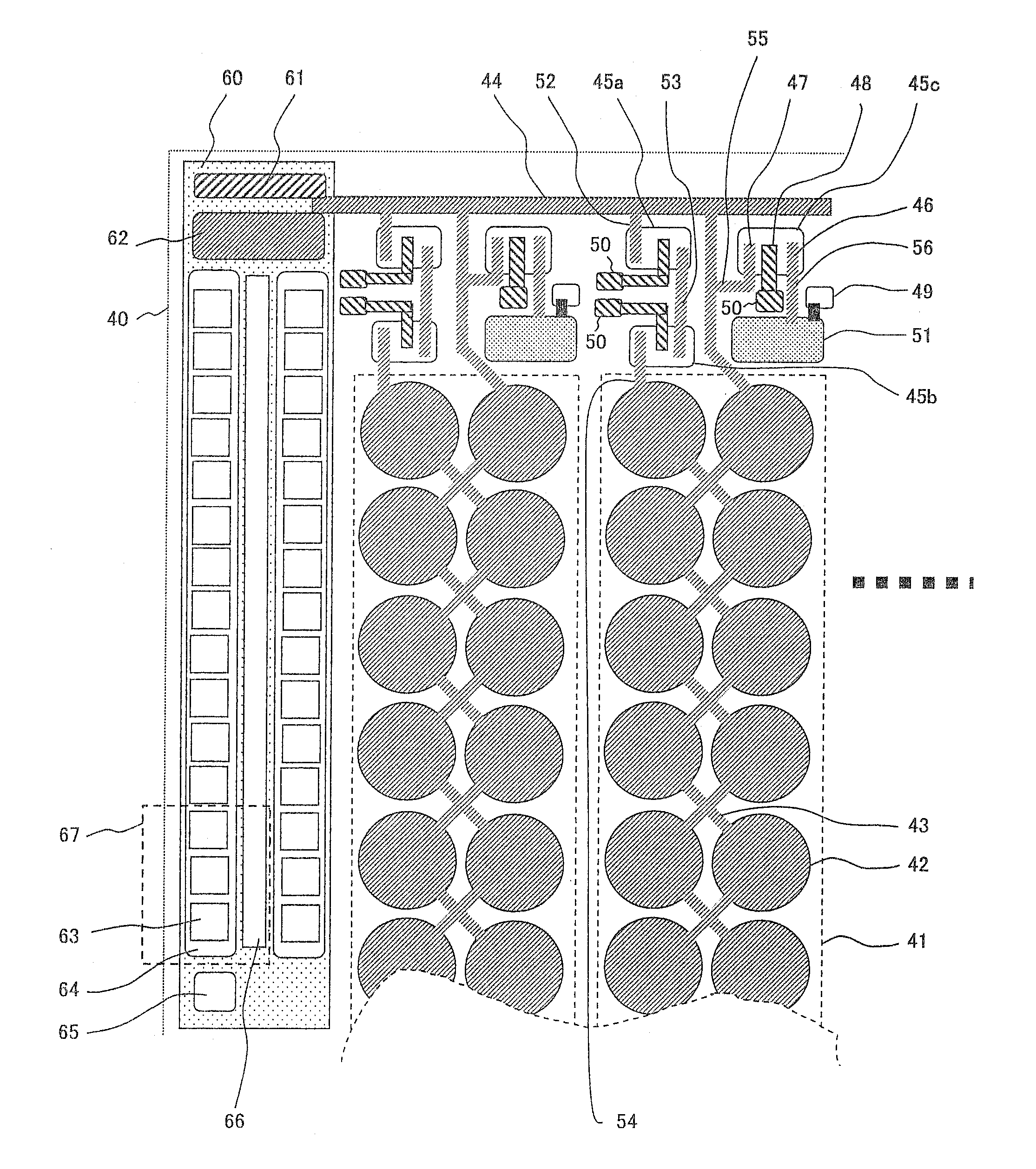
[0062]Conventionally, miniature piezoelectric transformers and miniature electromagnetic transformers have been produced in a discrete manner and have been arranged close to cMUTs and pMUTs. However, in this method, the size of electric circuits can only be reduced to some extent, and a high level of quality management has been required because of complicated wiring and connection.

[0063]Meanwhile, to form a high-voltage generation unit on or in a silicon substrate that is the same as an ultrasonic transducer produced by using the micromachining process has not been suggested conventionally.

[0064]Accordingly, by using the micromachining process or the semiconductor integration process, the present invention forms a DC high-voltage generation unit on or in a silicon substrate that is the same as an ultrasonic transducer produced by using the micromachining process. Thereby, the reduction of the size of the cMUT devices is realized.

[0065]In other words, in a cMUT according to the prese...


PUM


Abstract

A capacitive micromachined ultrasonic transducer (cMUT) device, comprising: a cMUT formed on a semiconductor substrate; a DC high-voltage generation unit that is provided on the semiconductor substrate and that is for generating a DC high-voltage signal to be superposed on a driving signal for the cMUT; a driving signal generation unit that is provided on the semiconductor substrate and that is for generating the driving signal; and a superposition unit that is provided on the semiconductor substrate and that is for branching the DC high-voltage signal output from the DC high-voltage generation unit and for superposing one of the branched DC high-voltage signals on the other of the branched DC high-voltage signals via the driving signal generation unit.

Description

CROSS REFERENCE TO RELATED APPLICATION[0001]This is a Continuation Application of PCT Application No. PCT / JP 2006 / 319744, filed Oct. 3, 2006, which was not published under PCT Article 21(2) in English.[0002]This application is based on and claims the benefit of priority from the prior Japanese Patent Application No. 2005-289823 filed in Japan on Oct. 3, 2005, the entire contents of which are incorporated by this reference.BACKGROUND OF THE INVENTION[0003]1. Field of the Invention[0004]The present invention relates to ultrasonic transducer devices that are included in ultrasound scopes, in ultrasound miniature probes, and in ultrasound capsule endoscopes, and that are manufactured by using the micromachining processes, and also relates to a method of controlling the same.[0005]2. Description of the Related Art[0006]The diagnostic ultrasound method, in which ultrasound is emitted onto walls of body cavities and the state of the body is visualized on the basis of the signals echoed fro...

Claims


Application Information

Patent Timeline
Patent Type & Authority Applications(United States)
IPC IPC(8): A61B8/00B06B1/02H01L41/09
CPCA61B8/00A61B8/12G01N29/2406B06B1/0292B06B2201/51B06B1/0207
Inventor ADACHI, HIDEOWAKABAYASHI, KATSUHIROTAMIYA, KOSEIAMIKURA, MASAAKIMATSUMOTO, KAZUYAOHTA, RYOHASEGAWA, MAMORUITO, HIROSHI
Owner OLYMPUS CORP
Learn More