
Calibration of ship attitude reference

a technology of attitude determination and reference, which is applied in the direction of navigation instruments, vessel construction, instruments, etc., can solve the problems of undesired differences between local reference frames, incorrect interpretation, and incorrect initial direction of anti-missiles launched by remote sites

Inactive Publication Date: 2008-10-30
LOCKHEED MARTIN CORP
View PDF3 Cites 42 Cited by
  • Summary
  • Abstract
  • Description
  • Claims
  • Application Information

AI Technical Summary

Problems solved by technology

The picket ship may attempt to engage and destroy the hostile missile, but may be unable to because of the head start of the hostile missile before it is initially detected.
However, when sensed information from a picket ship is sent to other ships or platforms, there is a potential for error attributable to undesired differences between the local reference frames and a true reference frame or geodetic coordinates.
These differences, if not taken into account, can result incorrect interpretation of the data at the remote or data-receiving site, which in turn may cause the antimissile launched by the remote site to initially be directed incorrectly.
If the antimissile is initially launched in an incorrect direction, it may not be possible to correct the heading of the antimissile in time to destroy the hostile missile or target.
The relative gridlock technique is cumbersome.
Such inertial navigation systems are subject to drift and bias errors, so the data indicative of attitude may be incorrect on each intercommunicating ship.
This procedure is lengthy, and may take as much as 72 hours due to the need for correction of the gyros for the Earth's rotation, which is at a relatively slow rate.
At sea following the static calibration, recalibration of the inertial navigation system is not performed for lack of a suitable calibration method.
Thus, the inertial navigation systems of each of the ships involved in a multiple-platform defense against hostile ballistic-type missiles tend to drift relative to each other, giving rise to unwanted errors which cumulatively may degrade antimissile defense.

Method used


Image

  • Calibration of ship attitude reference
  • Calibration of ship attitude reference
  • Calibration of ship attitude reference

Examples


Embodiment Construction

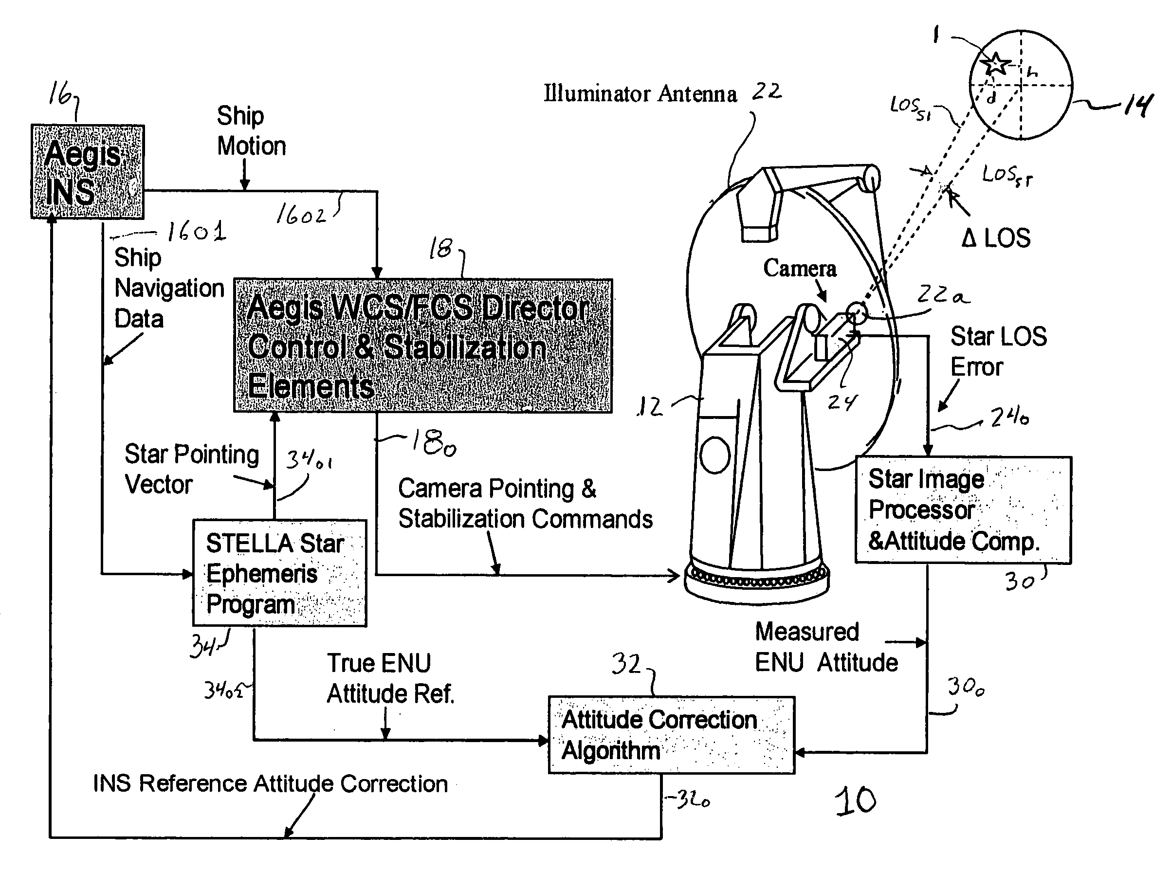
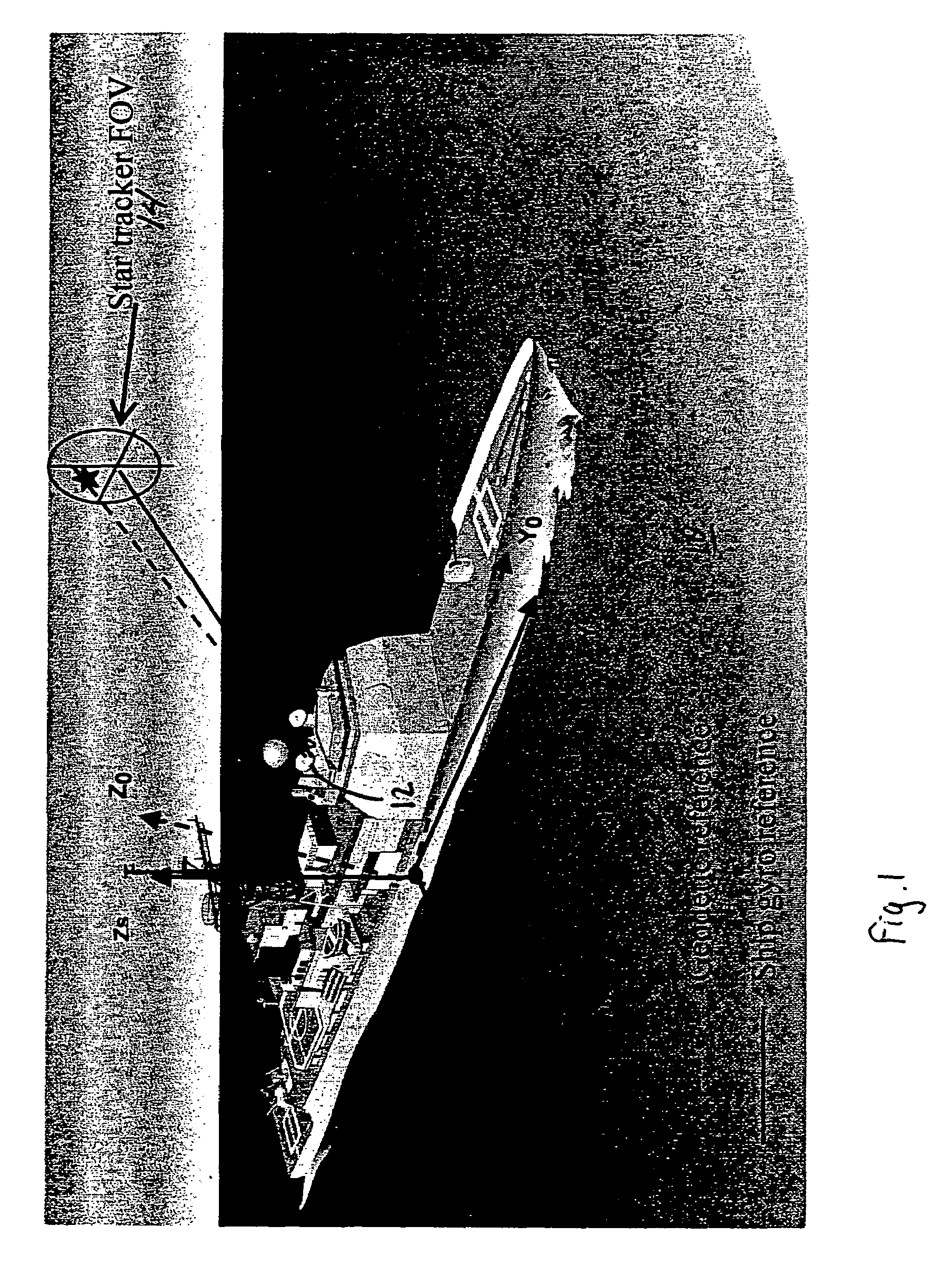
[0018]According to one aspect of the invention, a star tracker camera is mounted on a “gimbal” platform which is stabilized against attitude motion by the ship's local inertial navigation system (INS). The star tracker camera is directed toward first and second selected stars using a suitable ephemeris, and the azimuth and elevation error between each of the stars and the “boresight” or line-of-sight of the star tracker is noted. A vector triad is formed representing the attitude of the ephemeris, and another vector triad is formed representing the inertial navigation system attitude. These triads are processed together to determine the coordinate transformation matrix between the inertial navigation attitude and the ephemeris attitude. The coordinate transformation matrix is utilized with the inertial navigation attitude to generate calibrated attitude information. The hostile missile tracking information is either generated using the calibrated attitude information or is converted...


PUM


Abstract

A ship includes a star tracker mounted on a platform stabilized in ENU by the inertial navigation system (INS). The line-of-sight (LOS) of the star tracker is directed toward two separated stars, and the LOS difference angles are noted. The angles are processed to generate vector triads representing geodetic (ephemeris) and navigation system attitude. The triads are processed to generate a coordinate transformation matrix. The transformation matrix is separated into systematic error and reference attitude error. The reference attitude error is summed with the inertial navigation system attitude to generate corrected ENU attitude. The corrected attitude is used as a reference for shipboard sensors, to reduce errors when the sensor data is linked to other platforms.

Description

FIELD OF THE INVENTION[0001]This invention relates generally to calibration of a ship's attitude determination system to true geodetic attitude.BACKGROUND OF THE INVENTION[0002]Naval ships have in the past been used in attack modes, which is to say for striking at the ships, aircraft and terrain of hostile powers. In conjunction with Ballistic Missile Defense (BMD) efforts, ships are increasingly being adapted for defense of a territory against ballistic missiles by being outfitted with equipment for surveillance, ballistic missile target tracking, target discrimination, target typing, and target cueing. In many cases, ships are provided with anti-ballistic-missile capabilities, such as antimissiles for destroying missiles, including intercontinental missiles, which are a threat to friendly territory. Various ballistic missile detection, tracking, and antimissile guidance systems are described in U.S. patent application Ser. Nos. 11 / 356,675 filed Feb. 16, 2006 in the name of Denis e...

Claims


Application Information

Patent Timeline
Patent Type & Authority Applications(United States)
IPC IPC(8): B64G1/24
CPCB63B9/08B63G9/00B63J2099/008G01C21/025G01C21/165G01S3/7867G01C25/005G01C21/203G01C21/1656
Inventor LUK-PASZYC, JERZY W.STETSON, JOHN B.
Owner LOCKHEED MARTIN CORP
Learn More