Method for making an optical preform

a manufacturing method and optical taper technology, applied in glass production, glass making equipment, manufacturing tools, etc., can solve problems such as optical taper, and achieve the effects of reducing the stress that is built into the deposited glass layers during the vapor deposition process, and increasing the usable preform length

Active Publication Date: 2008-11-06
DRAKA COMTEQ BV
View PDF18 Cites 6 Cited by
  • Summary
  • Abstract
  • Description
  • Claims
  • Application Information

AI Technical Summary

Benefits of technology

[0018]The present inventors have surprisingly found that the aforementioned maximum value for the refractive index near the substrate tube's supply side can be reduced by shifting the position of the reversal point near the substrate tube's supply side along the longitudinal axis of the substrate tube during at least part of step (iii). Within this context, the inventors have further found that the effect on the geometric taper is negligible and that it has thus become possible to increase the usable preform length.
[0019]Although the taper effect is less pronounced on the substrate tube's discharge side than on the substrate tube's supply side, it is also possible to shift the position of the reversal point near the discharge side during at least part of step (iii). The stress that is built into the deposited glass layers during the vapor deposition process is thereby reduced.
[0020]In one embodiment, the position of the reversal point near the substrate tube's supply side shifts away from the discharge side. Such a shift makes it possible to increase the usable preform length.

Problems solved by technology

One of the problems of the methods according to the above-cited documents is the fact that an optimization of the geometric taper will lead to optical taper and vice versa.

Method used


Image

  • Method for making an optical preform
  • Method for making an optical preform
  • Method for making an optical preform

Examples


examples

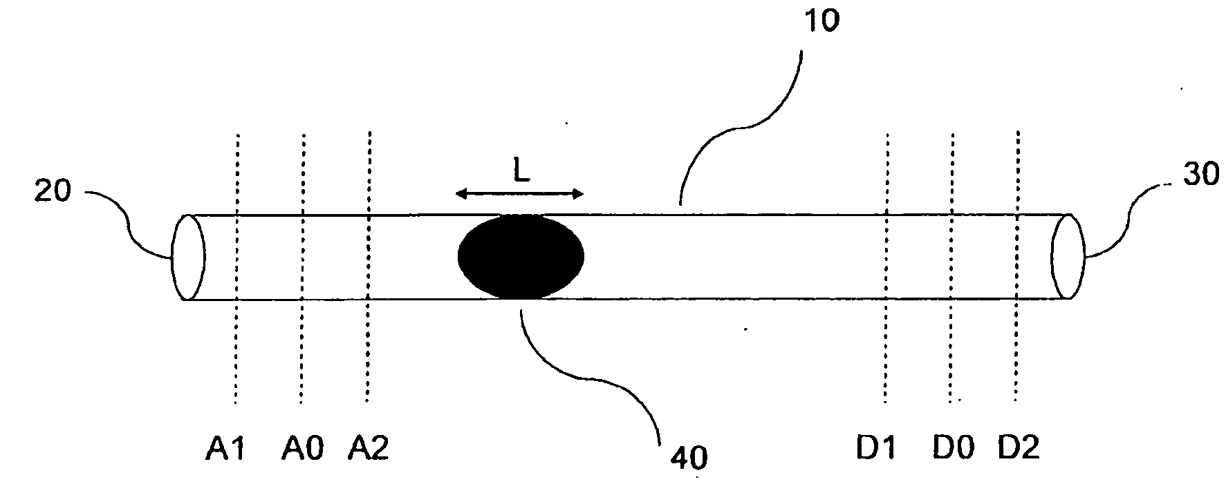
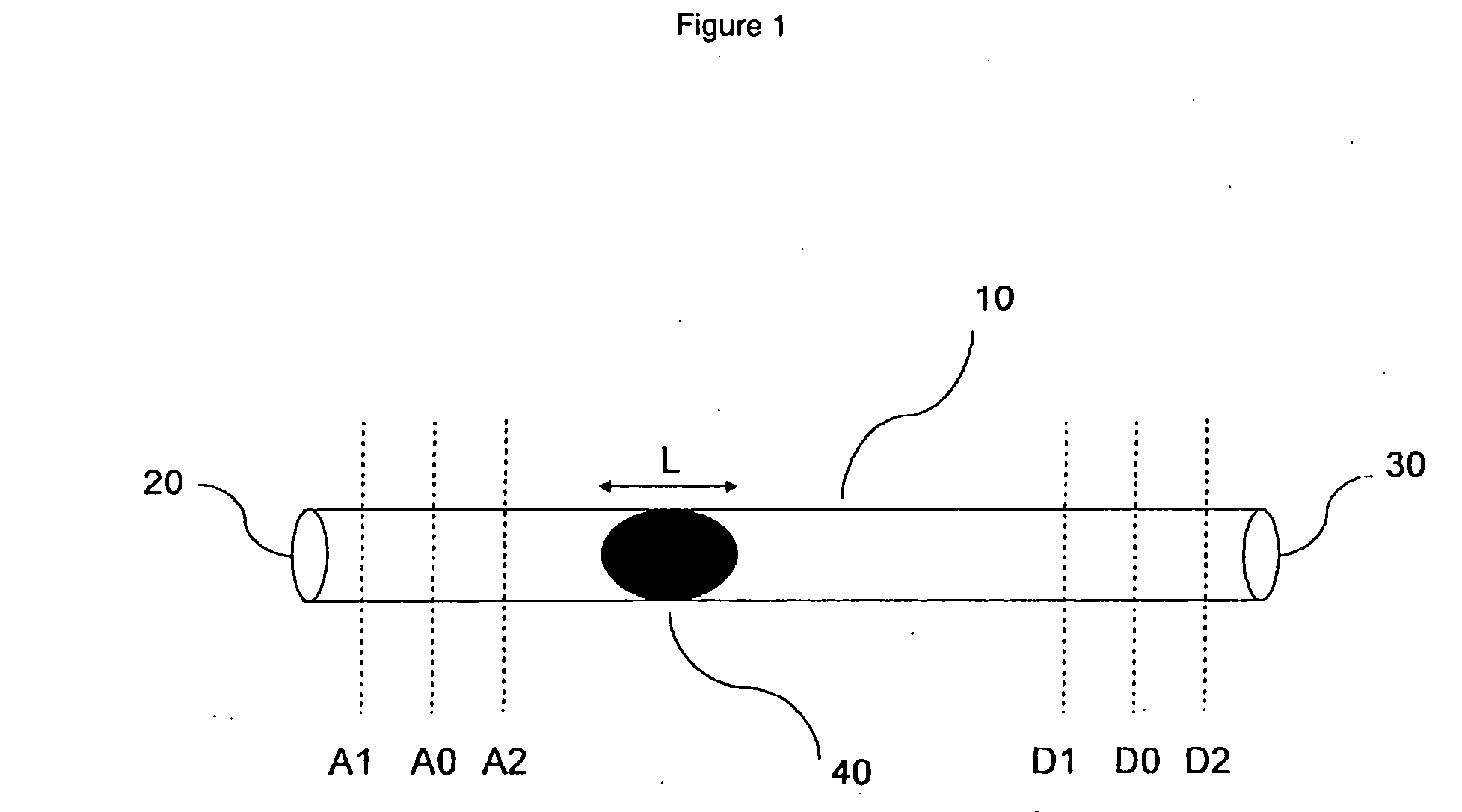
[0060]Preforms for forming optical fibers having a radial refractive index profile as shown in FIG. 4 are manufactured via the method according to the present invention. The reversal point near the supply side shifts in the direction away from the discharge side during the entire step (iii). In FIGS. 1 and 2, this means that the reversal point near the supply side shifts from A0 to A1 during step (iii). The plasma length L is about 200 millimeters, and the shift takes place linearly with time. The total shift is varied, and the effect thereof on the usable preform length is determined.

TABLE 1exampletotal shift (mm)usable preform length (mm)No shift01000I201010II501030III701050IV1001050V110980

[0061]It has been observed that preforms manufactured according to the present invention exhibit a reduction of about five percent with respect to layer cracking. By way of example, such a five percent reduction might represent an improvement in the incidence of layer cracking from seven percent...


PUM

PropertyMeasurementUnit
lengthaaaaaaaaaa
lengthaaaaaaaaaa
lengthaaaaaaaaaa

Abstract

The present invention relates to a method for manufacturing a preform for optical fibers via a vapor deposition process in which the position of the reversal point near the substrate tube's supply side shifts along the longitudinal axis of the substrate tube during at least part of the deposition process.

Description

CROSS-REFERENCE TO PRIORITY APPLICATION[0001]This application claims the benefit of pending Dutch Application No. 1033773 for “A Method for Manufacturing a Preform as well as an Optical Fibre to be Obtained Therewith” (filed Apr. 27, 2007, at the Dutch Patent Office) via 35 U.S.C. § 119. Dutch Application No. 1033773 is hereby incorporated by reference in its entirety.FIELD OF THE INVENTION[0002]The present invention relates to a method for manufacturing a preform for optical fibers using a vapor deposition process, including the steps of (i) providing a hollow glass substrate tube having a supply side and a discharge side, (ii) supplying doped or undoped glass-forming gases to the interior of the substrate tube via its supply side, (iii) creating plasma conditions within the interior of the substrate tube for depositing glass layers on the inner surface of the substrate tube by moving the plasma back and forth along the longitudinal axis of the substrate tube between a reversal poi...

Claims


Application Information

Patent Timeline
Patent Type & Authority Applications(United States)
IPC IPC(8): C03B37/018
CPCC03B37/0183Y02P40/57
Inventor DECKERS, ROB HUBERTUS MATHEUSKORSTEN, MARCOCREMERS, ROBERT MARTINUS MARIEDE JONGH, KOEN
Owner DRAKA COMTEQ BV
Why Eureka
Try Eureka