Control apparatus for an aircraft

a control apparatus and aircraft technology, applied in the field of aircraft control apparatus, can solve the problems of increasing complexity and exacerbated problems of the control apparatus, and achieve the effect of simple conversion of the sensor and easy attachment of the sensor

Inactive Publication Date: 2008-11-06
LIEBHERR AEROSPACE LINDENBERG
View PDF8 Cites 14 Cited by
  • Summary
  • Abstract
  • Description
  • Claims
  • Application Information

AI Technical Summary

Benefits of technology

[0003]Starting from this, it is the underlying object of the present invention to provide an improved control apparatus of the aforesaid type which avoids disadvantages of the prior art and further develops the latter in an advantageous manner. A simple control apparatus with few components should preferably be provided which facilitates the attachment of the sensors and actuators and permits a simple conversion of the sensor and actuator components for different control designs.
[0006]The two control shafts advantageously have fixed outputs so that the assembly of control modules associated with the respective control shafts is considerably simplified. No moving connector lines have to be provided since the sensors and actuators can be installed in a fixed manner at the housing. In addition, low moving masses can be achieved since attached sensor or actuator components are not moved along. In addition, a high reliability and a simple inner structure of the control apparatus can be achieved by a low number of components. Above all things, however, a modular utilization of the control apparatus as an active or passive joystick is possible since the components required in each case for the different embodiments of the control can be attached and / or replaced in a modular form.
[0011]The hoop is preferably made with two shells to achieve a double load path and thus to increase safety.
[0012]The slotted hoop can be doubly journaled. It is preferably rotatably journaled on oppositely disposed sides or is connected to the associated second control shaft. The double journaling of the hoop allows its movements to be picked up doubly or to attach different sensor and / or actuator components. In addition to a simply redundant design, a simple conversion capability can also hereby be achieved.

Problems solved by technology

The problem is exacerbated as the complexity of the control apparatus increases.

Method used


Image

  • Control apparatus for an aircraft
  • Control apparatus for an aircraft

Examples


Embodiment Construction

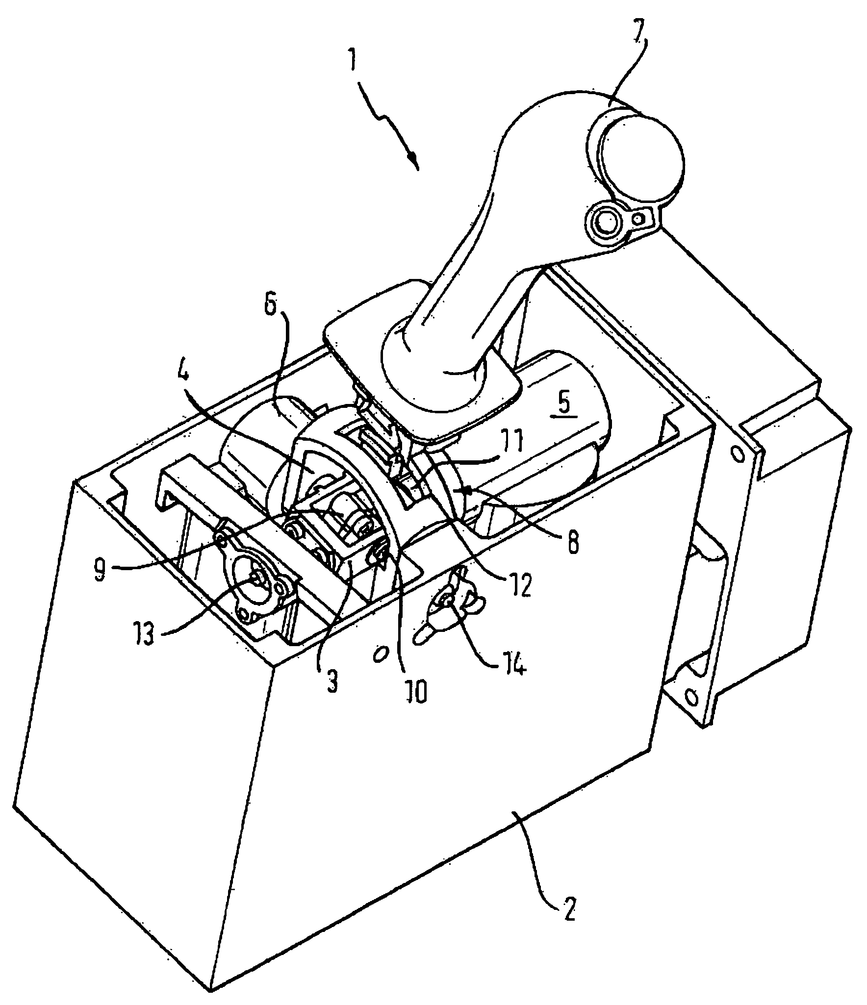
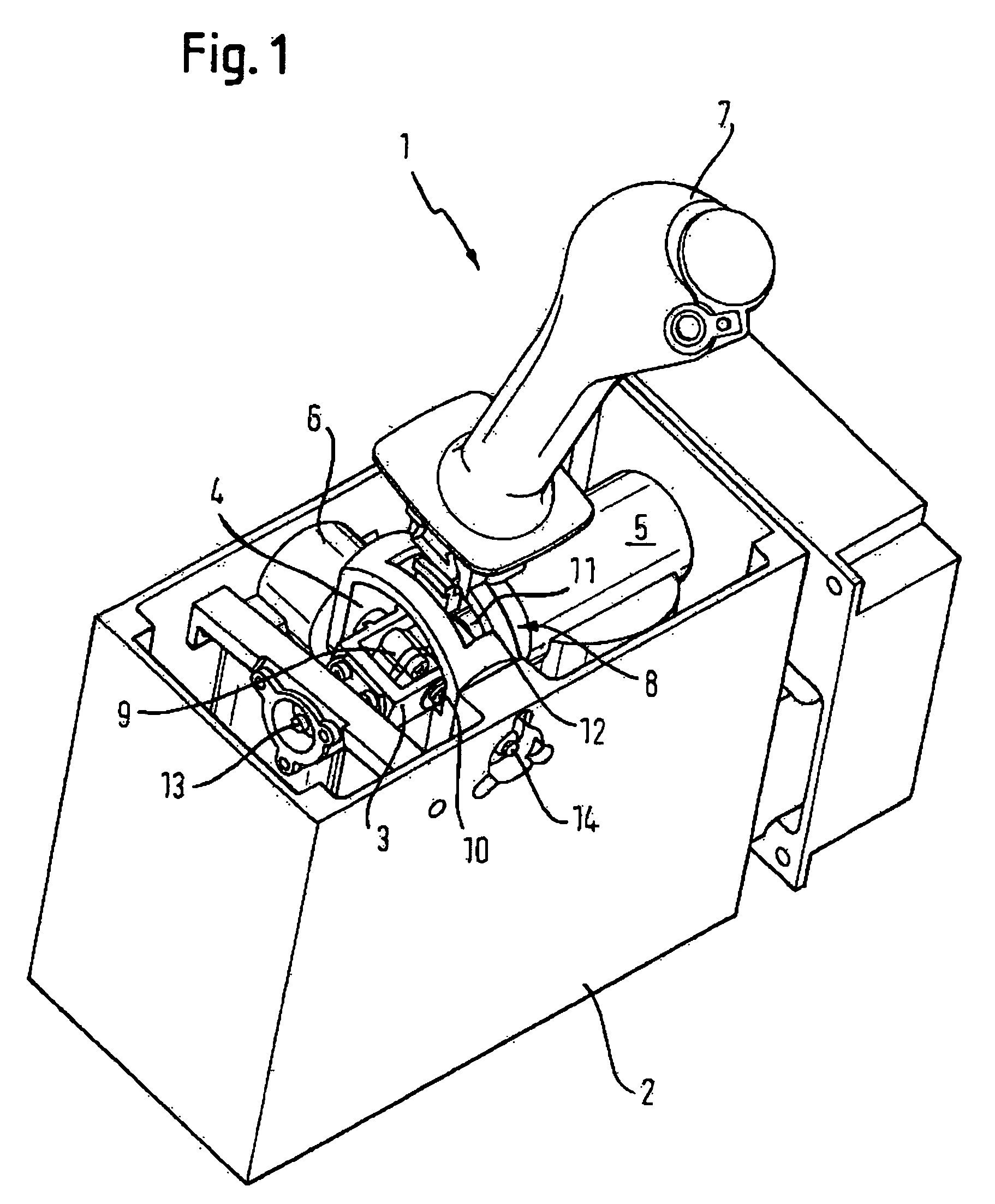
[0018]The control apparatus 1 drawn in the FIGURE comprises a box-shaped housing 2 in which two control shafts 3 and 4 are journaled in a fixed manner, with the control shafts 3 and 4, however, naturally being rotatably journaled so that they can be rotated around their longitudinal axes. In the drawn embodiment, actuator motors 5 and 6, which are likewise received in the interior of the housing 2 and are rigidly installed to it, are flanged to the two control shafts 3 and 4.

[0019]A joystick 7 is connected to the two control shafts 3 and 4 via a Cardan-like joint 8 having two pivot axes extending transversely to one another. The joint 8 is made such that the two pivot axes stand perpendicular to one another and coincide with the two fixedly installed control shafts 3 and 4.

[0020]Specifically, the joint 8 in the drawn embodiment comprises a first joint part 9 which is connected to the first control shaft 3, and indeed around a transverse axis 10 extending perpendicular to the said fi...


PUM


Abstract

The present invention relates to a control apparatus for an aircraft comprising a multiaxially tiltable joystick for the actuation of at least two control transducers for the pitch and roll control of the aircraft, with the control transducers being associated with two control shafts which are connected to the joystick via a Cardan-like joint with two pivot axes aligned transversely to one another, with a pitch movement of the joystick being able to be converted via said joint into a rotation of the one control shaft and a roll movement of the joystick being able to be converted into a rotation of the other control shaft. In accordance with the invention, the control apparatus is characterized in that the two control shafts are rotatably journaled in a fixed manner at a common rack and in that the joint in each case has a freewheel with respect to the control shafts for tilt movements of the joystick in a plane parallel to the respective control shaft.

Description

BACKGROUND OF THE INVENTION[0001]The present invention relates to a control apparatus for an aircraft comprising a multiaxially tiltable joystick for the actuation of at least two control transducers for the pitch and roll control of the aircraft, with the control transducers being associated with two control shafts which are connected to the joystick via a Cardan-like joint with two pivot axes aligned transversely to one another, with a pitch movement of the joystick being able to be converted via said joint into a rotation of the one control shaft and a roll movement of the joystick being able to be converted into a rotation of the other control shaft.[0002]Joysticks of aircraft are typically tiltable biaxially, that is around a transverse axis to the front and rear, on the one hand, and around a longitudinal axis to the left and right, on the other hand. Control shafts are actuated by the corresponding tilt movements and their rotation is detected by transducers and is transforme...

Claims


Application Information

Patent Timeline
Patent Type & Authority Applications(United States)
IPC IPC(8): B64C13/04
CPCB64C13/04G05G9/047G05G2009/04718G05G2009/04766B64C13/0421
Inventor DECKER, WALTER ERNST
Owner LIEBHERR AEROSPACE LINDENBERG
Why Eureka
Try Eureka