
Self-calibrated integration method of light intensity control in LED backlighting

a technology of intensity control and led backlighting, which is applied in the direction of static indicating devices, optical radiation measurement, instruments, etc., can solve the problems of led lighting capability degrading through its life span, reduce wavelength and luminance shifting, increase or maintain led life span and lighting quality, and reduce heat and junction temperature generated during the time when leds are turned on.

Inactive Publication Date: 2008-11-06
LEE CHERN JIANN
View PDF8 Cites 27 Cited by
  • Summary
  • Abstract
  • Description
  • Claims
  • Application Information

AI Technical Summary

Benefits of technology

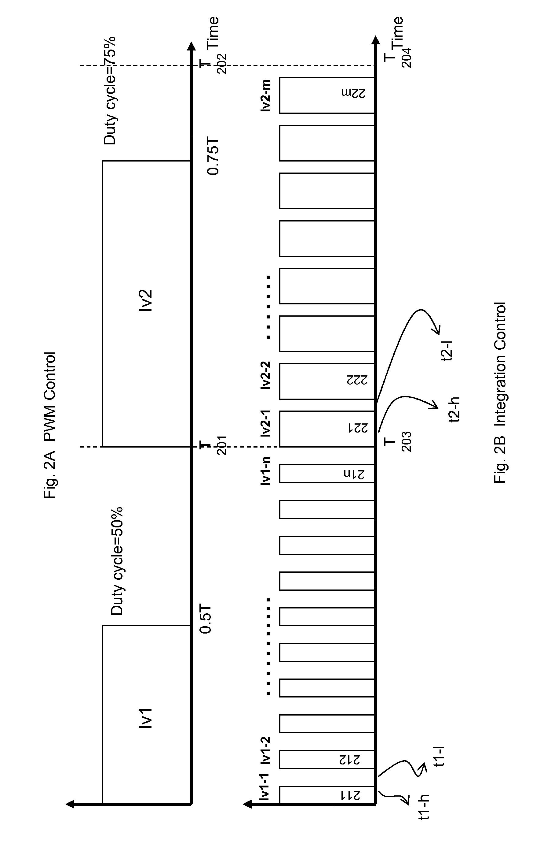
[0006]In order to increase or maintain the LEDs life span and lighting quality, the heat and junction temperature generated during the time when the LEDs are turned on must be reduced. This invention implements a technology to subdivide the PWM intervals for a required Duty Cycle when displaying the images. The subdivisions of the PWM intervals increase the frequencies of turning-off the LEDs before the heat and junction temperatures are accumulated. The total subdivisions of turning-on intervals remains the same for a required Duty Cycle. The current invention does not compromise the displaying requirements because human eyes inherently have the integration function to light luminance and colors. The sub-divided time periods of turning-on and turning-off of the LEDs are sufficient and long enough for the human eyes to build the images and wait for the next image light. By cooling off the heat and junction temperature more often before its accumulated, the wavelength and luminance shifting are reduced and therefore the LEDs lighting quality is maintained and improved.

Problems solved by technology

Instead, the LEDs lighting capability degrades through its life span and mainly caused by the increasing heat and junction temperatures.

Method used


Image

  • Self-calibrated integration method of light intensity control in LED backlighting
  • Self-calibrated integration method of light intensity control in LED backlighting
  • Self-calibrated integration method of light intensity control in LED backlighting

Examples


Embodiment Construction

Terminology and Lexicography:

[0015]Latching: The function of receiving data from a data bus and storing the data in a register or memory.

Frame Time: The time period of displaying an image on a displaying system. A common practice of the Frame Time is 1 / 60 seconds although the Frame Time may be implemented differently for various application requirements.

2bd: Two (2) to the power of bd, wherein bd is an integer.

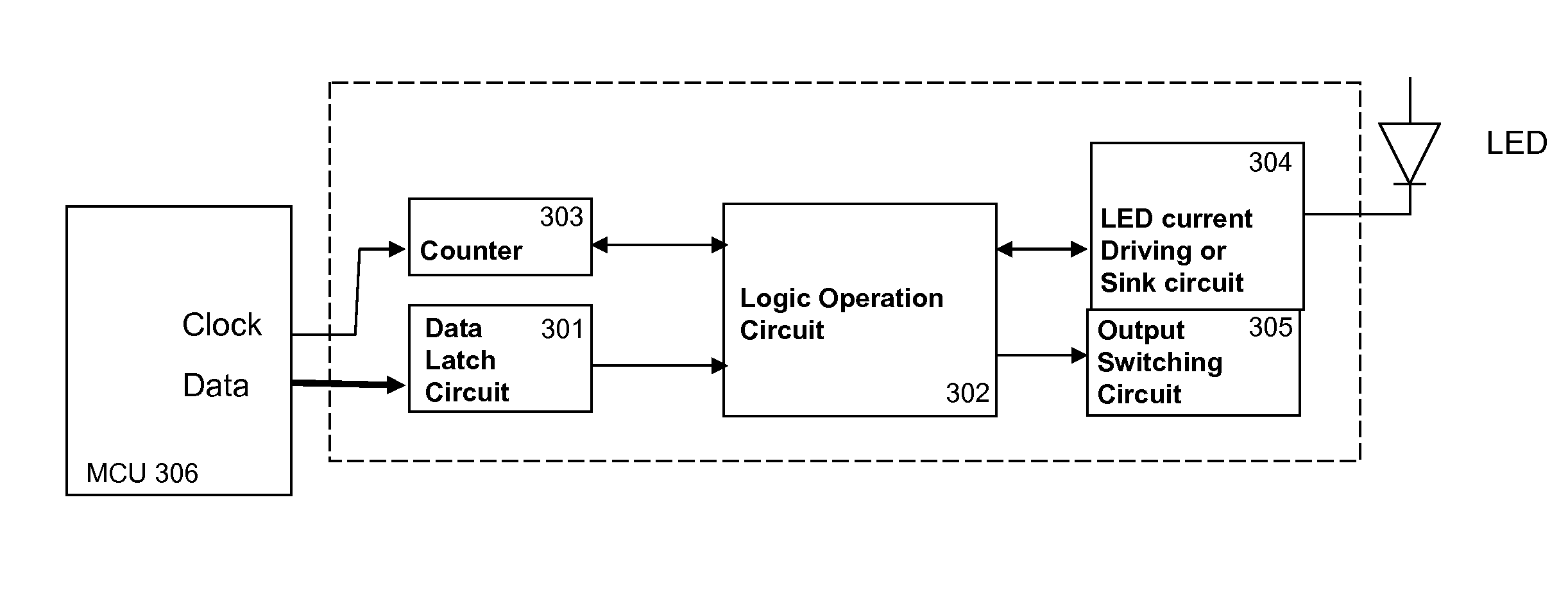
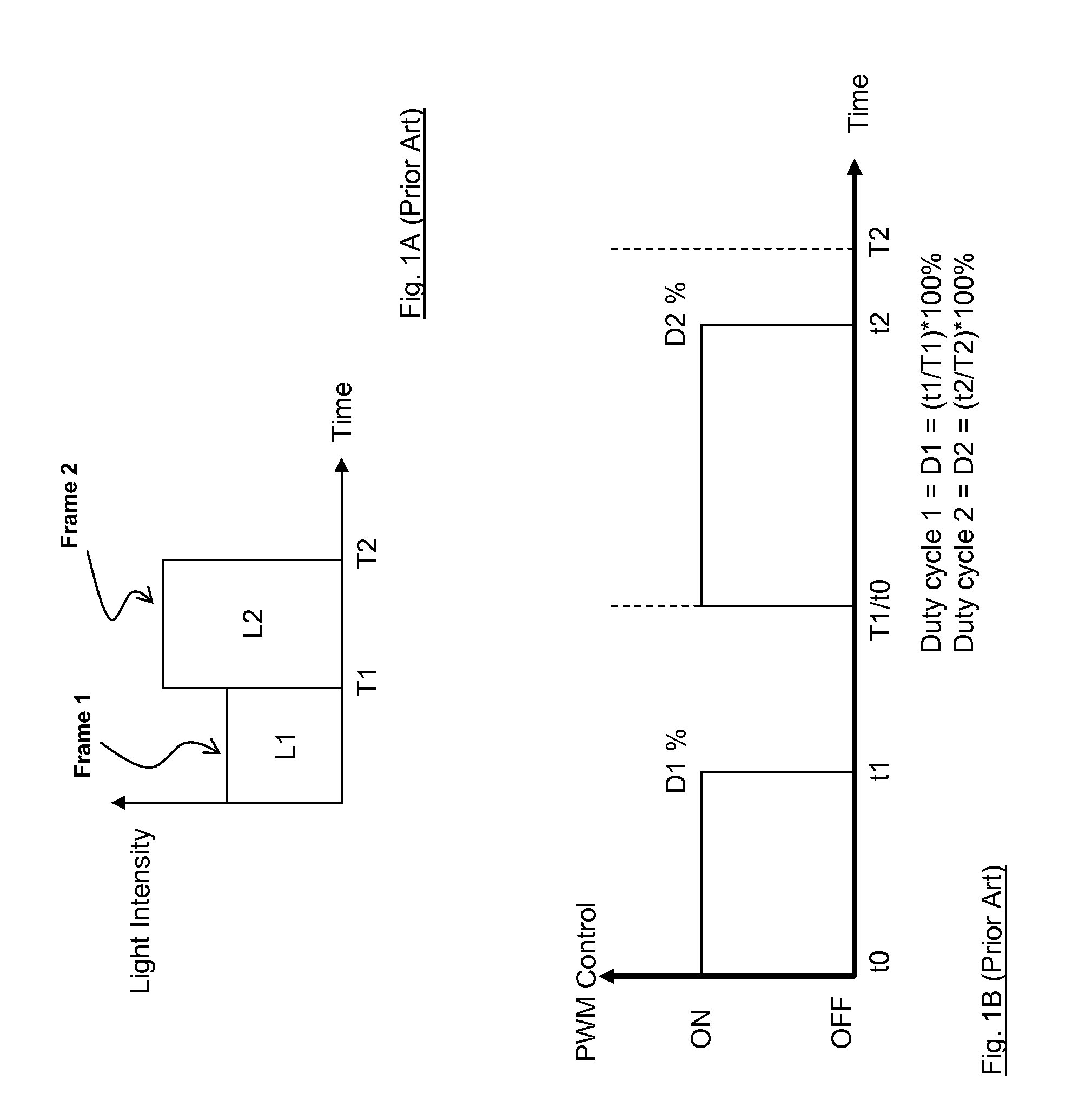
[0016]The PWM technology has been conventionally implemented to control the LED backlight brightness. The FIG. 1A shows the desired image light intensity L1 and L2 in the frame time T1 and T2. The FIG. 1B shows the PWM control on the L1 and L2 as illustrated by the FIG. 1A. For the frame time T1, the control signal generated by a MCU (306) turns on the LED from time t0 to t1 and turns off the LED for rest of the time within T1 frame time. The t1, or the Duty Cycle (D1) determines the light intensity of frame 1. The t2, or the Duty Cycle (D2), determines the light intensity of ...


PUM


Abstract

This invention is an LED lighting intensity control by subdivision of PWM intervals to resolve the wavelength and luminance shifting problems that are caused by increasing heat and junction temperatures.

Description

FIELD OF INVENTION[0001]This invention relates to an intensity control technology on Light Emitting Diode (LED) in order to resolve the problems of LED light wavelength and luminance shifting.BACKGROUND OF INVENTION[0002]The LED technology has been widely used in various applications for backlighting purposes. In order to display the images by using LEDs, the brightness of LEDs is a major consideration and technology to be implemented. The industries have been implementing Pulse Width Modulation (PWM) in controlling the LED backlight brightness. The LED is turned on during its Duty Cycle according to the control of the MCU (Micro Control Unit) in accordance with each Frame Time. Therefore, the temperature or the heat is generated through the duration of turning-on the LEDs until the end of its Duty Cycle.[0003]The current invention takes advantage of the integration function that human eyes inherently bear, by scaling and subdividing the PWM intervals in order to reduce the continuo...

Claims


Application Information

Patent Timeline
Patent Type & Authority Applications(United States)
IPC IPC(8): G01J1/32
CPCG09G3/3406G09G2320/064H05B33/0818H05B33/089H05B45/56H05B45/325
Inventor HUANG, HSIN CHIANGCHUNG, CHANG KUANG
Owner LEE CHERN JIANN
Learn More