Power generating plant

a power generation plant and power technology, applied in the direction of electric generator control, engine starters, turbine/propulsion engine ignition, etc., can solve problems such as the inability to solve the problem of generating plants

Active Publication Date: 2008-11-06
GENERAL ELECTRIC TECH GMBH
View PDF5 Cites 81 Cited by
  • Summary
  • Abstract
  • Description
  • Claims
  • Application Information

AI Technical Summary

Problems solved by technology

Such a power generating plant, therefore, does not solve two crucial problems which are very closely linked to its operation.

Method used


Image

  • Power generating plant
  • Power generating plant

Examples


Embodiment Construction

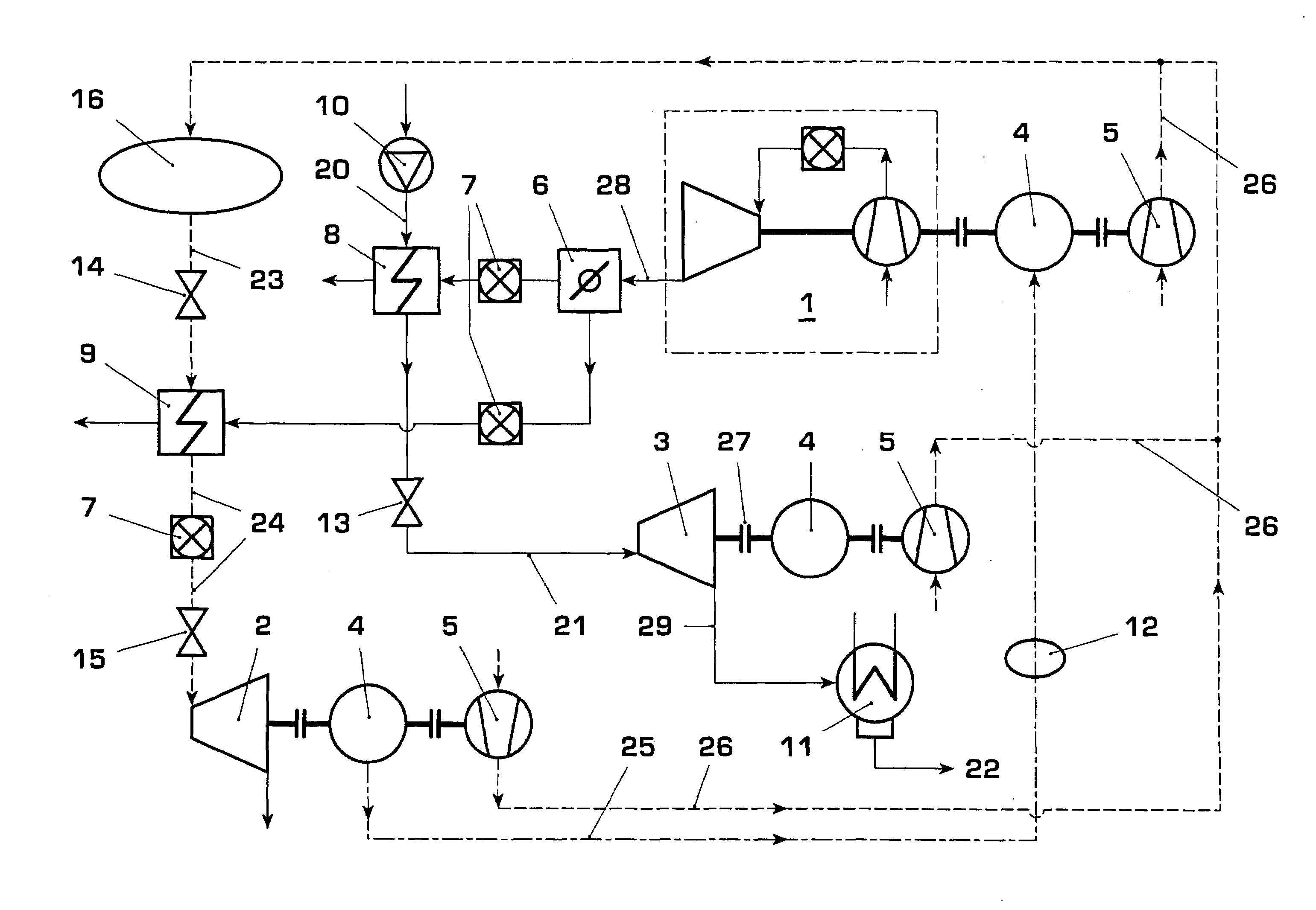
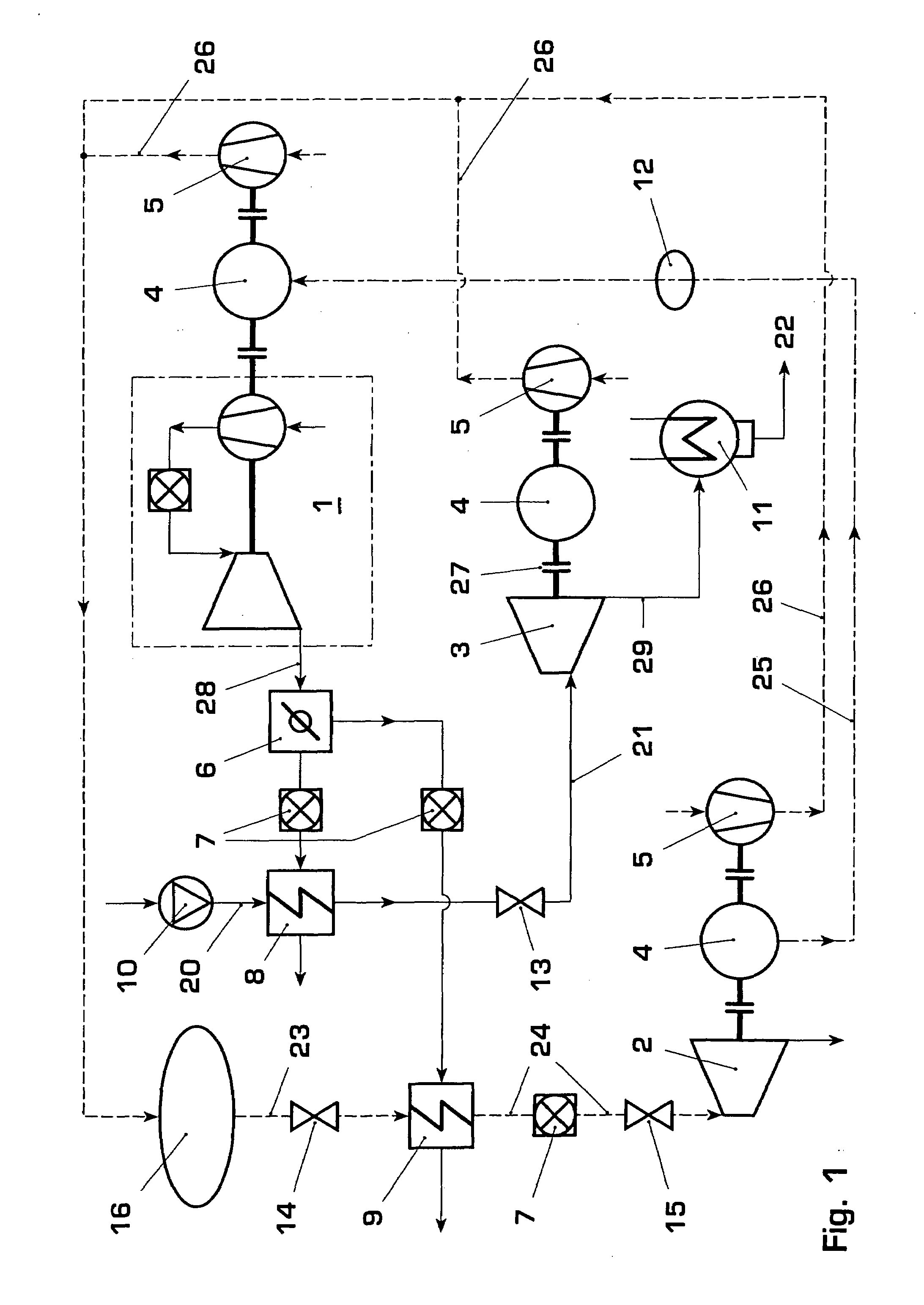
[0011]The power generating plant which is described for the prior art can be flexibly configured by means of an extension by the gas turbogroup being optionally combined with a steam cycle in such a way that the two cycles, which when individually considered per se are associated with the prior art, are to be brought together in an extremely synergetically and operationally very advantageous way. Such a power generating plant, specifically the gas turbogroup which is to be combined with a steam cycle and with a pressurized storage facility, first of all enables maximum operational flexibility.

[0012]The aforementioned weak point of such a power generating plant, which has no autonomy in the case of a “black start” having become necessary, can be eliminated by the potential of the pressurized storage facility being used in such a way that some of the air which is stored there being directed through the heat exchanger which is arranged on the outflow side. This heat exchanger, which is...


PUM


Abstract

During operation of a power generating plant, which essentially comprises a gas turbogroup, a compressed air accumulator, an air turbine which is equipped with at least one generator, the compressed air which is extracted from the compressed air accumulator is directed through a heat exchanger, which acts on the outflow side of the gas turbogroup, and is thermally conditioned there. This compressed air then charges the air turbine, wherein during a “black out” or other shutdown of the power generating plant, the electric current energy which can be obtained by means of the thermally conditioned compressed air in the air turbine, via a power line is used directly for start-up of the gas turbogroup.

Description

RELATED APPLICATIONS[0001]This application claims priority under 35 U.S.C. §119 to Swiss Application No. 01381 / 05 filed in the Swiss Patent Office on 23 Aug. 2005, and as a continuation application under 35 U.S.C. §120 to PCT / EP2006 / 065189 filed as an International Application on 9 Aug. 2006 designating the U.S., the entire contents of which are hereby incorporated by reference in their entireties.TECHNICAL FIELD[0002]A power generating plant is disclosed.BACKGROUND INFORMATION[0003]From the prior art, gas turbine power generating plants have become known in which the exhaust gas heat of a gas turbogroup is used for steam generation, wherein the steam can be supplied to multifarious applications. In combined cycle power generating plants, the steam is then expanded in a steam turbine in accordance with requirements, delivering power. The steam turbine drives a generator for power generation.[0004]Furthermore, a recuperative pressurized storage facility has become known, for example ...

Claims


Application Information

Patent Timeline
Patent Type & Authority Applications(United States)
IPC IPC(8): F02C6/00F02C6/04F02C6/16
CPCF01D19/00F02C6/16Y02E60/15F05D2260/85Y02E60/16
Inventor ALTHAUS, ROLF
Owner GENERAL ELECTRIC TECH GMBH
Why Eureka
Try Eureka