Electroluminescence device
- Summary
- Abstract
- Description
- Claims
- Application Information
AI Technical Summary
Benefits of technology
Problems solved by technology
Method used
Image

Examples
synthesis example 1
Synthesis of Exemplified Compound c-7
[0061]
[0062]In a 20-mL reaction vessel, XX-1 (0.5 g, 2.4 mmol) and XX-2 (0.5 g, 2.4 mmol) which were synthesized according to Journal of American Chemical Society, 91, 918 (1969) and a mixed solvent (8 mL) containing toluene and ethanol at 10:1(w / w) were added. Then, a 6N aqueous potassium hydroxide solution (1 mL) was slowly added dropwise to the resultant solution under stirring. The solution was heated to 75° C. and stirred at the same temperature for 10 minutes. After cooling to room temperature, the precipitated crystal was filtered off and washed with water and methanol to obtain XX-3 (0.8 g, yield=86%).
[0063]Next, in a 50-mL reaction vessel, XX-3 (0.8 g, 2.1 mmol), dichloroethane (16 mL), XX-4 (0.4 g, 2.3 mmol), and propylene oxide (0.5 g, 8.3 mmol) were added, followed by stirring at 70° C. for 1 hour.
[0064]The reaction solution was concentrated, and the reaction product was separated and purified by silica gel column chromatography (mobi...
synthesis example 2
Synthesis of Exemplified Compound c-37
[0069]
[0070]In a 300-mL reaction vessel, c-7 (3.0 g, 6.97 mmol) and chlorobenzene (150 ml) were added. Then, benzene boronic anhydride (70%) (7.15 g, 13.9 mmol) was added to the mixture, following by heating to 130° C. and stirring at the same temperature for 24 hours.
[0071]The reaction solution was concentrated, the reaction product was separated and purified by silica gel column chromatography (mobile phase:chloroform:hexane=1:1) to obtain a yellow powder XX-4 (3.0 g, 6.54 mmol, yield=93%).
[0072]In a 50-mL pressure-proof test tube, XX-4 (1.0 g, 2.18 mmol) and anhydrous dioxane (15 ml) were added. Then, diethylaminosulfur trifluoride (DAST) (90%) (2.34 g, 13.1 mmol) was added to the resultant mixture, followed by heating to 100° C. and stirring at the same temperature for 14 hours. After cooling to room temperature, diethylaminosulfur trifluoride (DAST) (90%) (2.34 g, 13.1 mmol) was further added to the resultant mixture, followed by heating to...
example 1
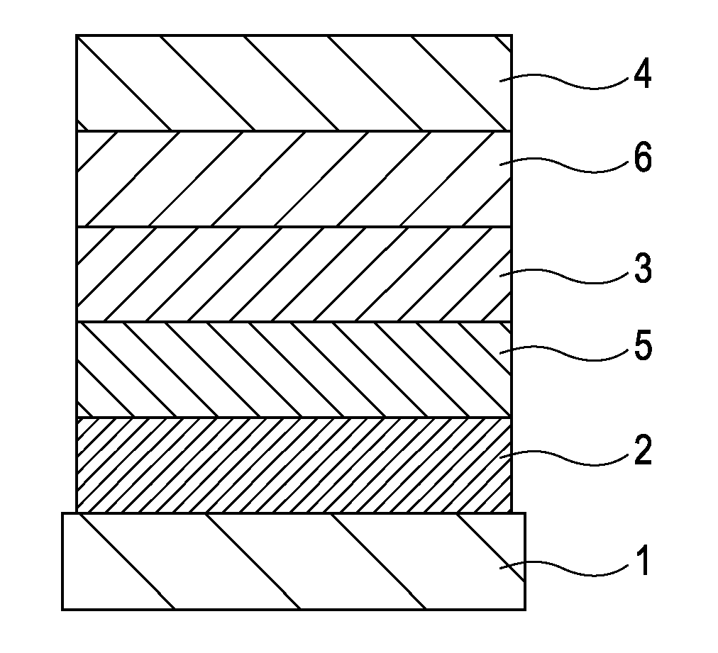
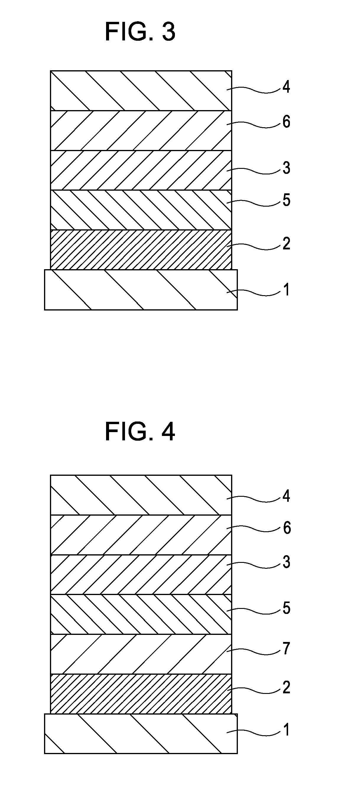
[0077]A device including three organic layers as shown in FIG. 3 was manufactured.
[0078]ITO (transparent electrode 2) of 100 nm was patterned on a glass substrate (transparent substrate 1). Then, organic layers and electrode layers, which will be described below, were continuously deposited on the ITO substrate by resistance-heating vacuum deposition in a vacuum chamber of 10−5 Pa so that the opposing area between electrodes was 3 mm2.
[0079]Hole transport layer (5) (40 nm): α-NPD
[0080]Luminescent layer (3) (30 nm): HOST-1: Exemplified Compound c-7 (weight ratio 5%)
[0081]Electron transport layer (6) (30 nm): Bphen (manufactured by Dojindo Laboratories)
[0082]Metal electrode (4-1) (1 nm): KF
[0083]Metal electrode (4-2) (130 nm): Al
[0084]With respect to the characteristics of the organic light-emitting device, current-voltage characteristics were measured by a microammeter 414OB manufactured by Hewlett-Packard, and luminance was measured by BM7 manufactured by Topcon Corporation. In the ...
PUM
| Property | Measurement | Unit |
|---|---|---|
| Luminescence | aaaaa | aaaaa |
Abstract
Description
Claims
Application Information
 - R&D Engineer
- R&D Manager
- IP Professional
- Industry Leading Data Capabilities
- Powerful AI technology
- Patent DNA Extraction
Browse by: Latest US Patents, China's latest patents, Technical Efficacy Thesaurus, Application Domain, Technology Topic.
© 2024 PatSnap. All rights reserved.Legal|Privacy policy|Modern Slavery Act Transparency Statement|Sitemap