Method and system for resolver alignment in electric motor system

a technology of electric motor system and resolver, which is applied in the direction of electric controllers, instruments, ignition automatic control, etc., can solve the problems of high frequency signal magnitude, high frequency signal method is poorly suited for machines with inherently low saliency, and high frequency signal cos

Inactive Publication Date: 2008-11-06
GM GLOBAL TECH OPERATIONS LLC
View PDF2 Cites 39 Cited by
  • Summary
  • Abstract
  • Description
  • Claims
  • Application Information

AI Technical Summary

Problems solved by technology

For large volume manufacturing, this alignment process may be costly, time consuming, and complicated.
Acoustic noise is generated when the high frequency signal has a large magnitude.
Further, the high frequency signal method is poorly suited for machines with inherently low saliency, such as surface mount PM motors.

Method used


Image

  • Method and system for resolver alignment in electric motor system
  • Method and system for resolver alignment in electric motor system
  • Method and system for resolver alignment in electric motor system

Examples


Embodiment Construction

[0013]The following detailed description is merely illustrative in nature and is not intended to limit the invention or the application and uses of the invention. Furthermore, there is no intention to be bound by any expressed or implied theory presented in the preceding technical field, background, brief summary or the following detailed description.

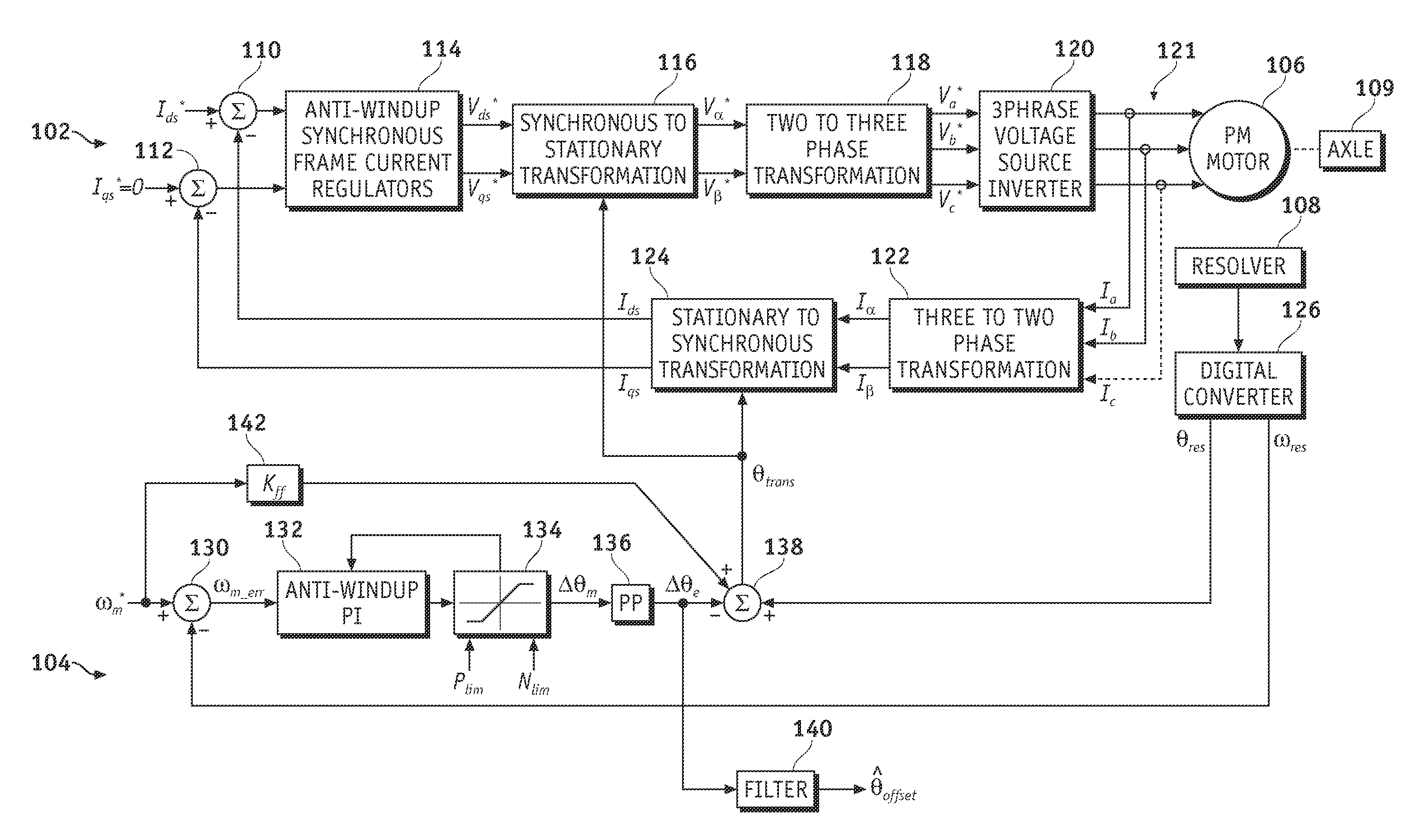
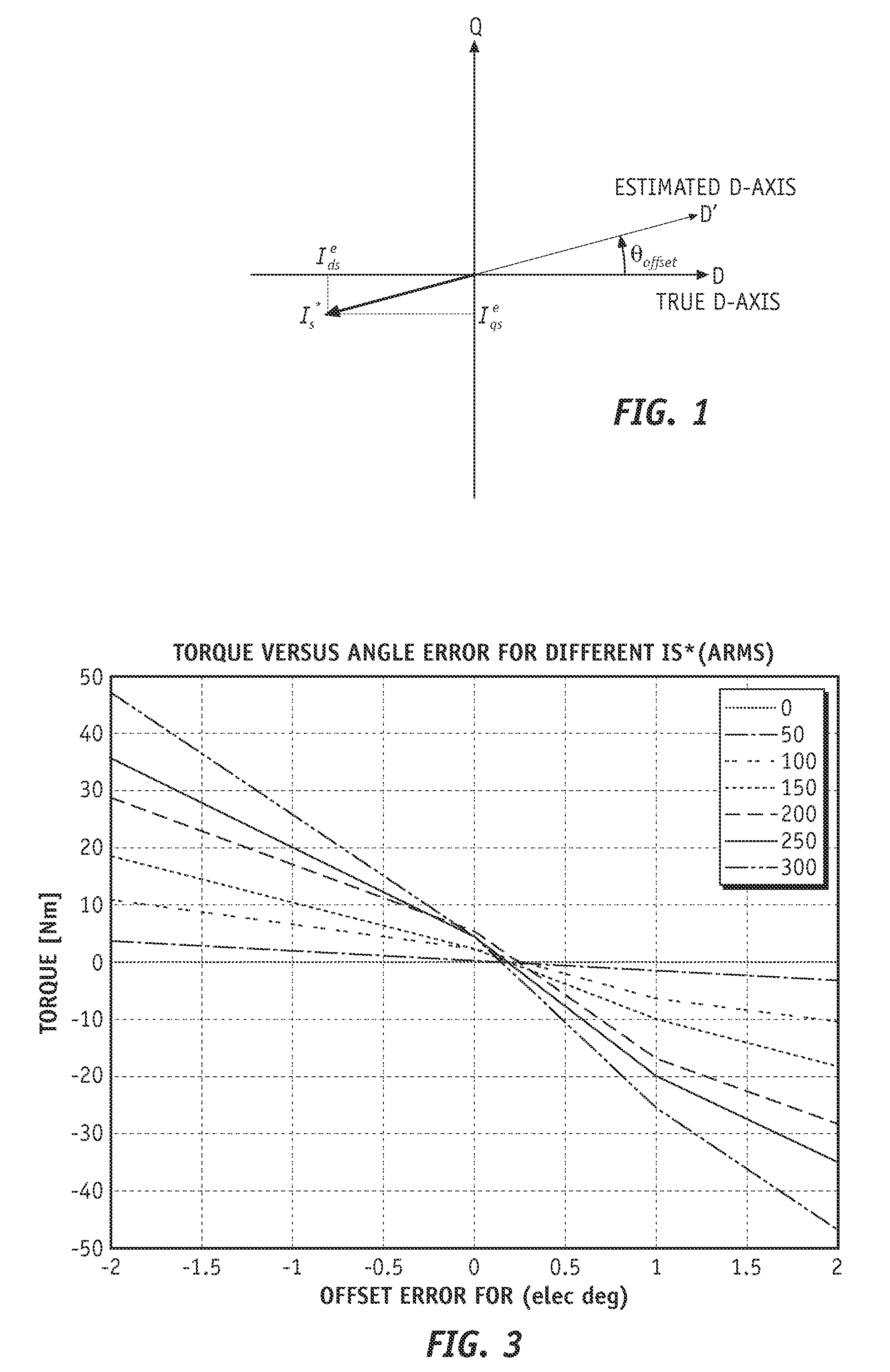
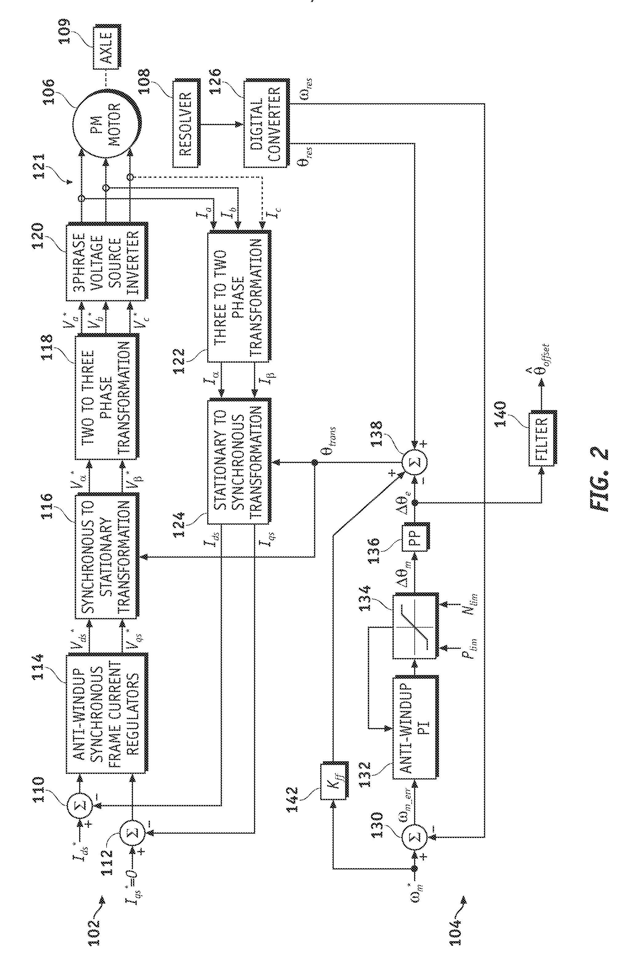
[0014]In an exemplary embodiment, a method and system are provided for aligning a resolver or other rotor position sensing device mounted to the machine rotor of an electric motor. Such electric motors are used in a variety of applications, including vehicle applications, and may be controlled via a voltage source inverter. If the electric motor operates without a load (e.g., without the electric motor being coupled to an axle in a vehicle application) and at a substantially constant rotational speed, a drag torque (e.g., resulting from lubricants and the like) is applied to the motor shaft. In general, the drag torque is relatively low...


PUM


Abstract

Methods and systems are provided for aligning a resolver in an electric motor system. The method includes commanding a d-axis current command and a speed command, operating an electric motor without a load in response to the d-axis current command and the speed command, determining a rotor speed in response to the speed command, and determining an offset of the resolver based on the speed command and the rotor speed when the rotor speed has substantially stabilized.

Description

TECHNICAL FIELD[0001]The present invention generally relates to determining rotor positions in electric motor systems, and more particularly relates to methods and apparatus for aligning resolvers.BACKGROUND OF THE INVENTION[0002]In some types of electric motors, controlling the motor is based in part on its rotor position. For example, permanent magnet (PM) synchronous motors utilize rotor position information for accurate torque control. The rotor position is typically measured with a resolver or a similar rotation sensing device. The rotor of the resolver is coupled to the machine rotor of the PM synchronous motor. For vector control, the resolver is generally aligned to the north pole of the machine rotor magnet (e.g., aligned with a controller d-axis). The accuracy by which the resolver can be aligned typically influences the accuracy and performance of the motor control.[0003]In some electric motors, the resolver is aligned during the assembly process. A high degree of precisi...

Claims


Application Information

Patent Timeline
Patent Type & Authority Applications(United States)
IPC IPC(8): H02P27/04G05B1/06G05B11/42
CPCH02P21/06H02P21/14H02P2203/05
Inventor SCHULZ, STEVEN E.GLEASON, SEAN E.WELCHKO, BRIAN A.
Owner GM GLOBAL TECH OPERATIONS LLC
Why Eureka
Try Eureka