Apparatus and method for referential position measurement and pattern-forming apparatus

a technology of which is applied in the field of apparatus and method for referential position measurement and pattern-forming apparatus, can solve the problems of little error, induced so-called telecentric error, and image taken by the camera has a correspondingly slight distortion, etc., and achieves high throughput efficiency.

Inactive Publication Date: 2008-11-06
FUJIFILM CORP
View PDF5 Cites 20 Cited by
  • Summary
  • Abstract
  • Description
  • Claims
  • Application Information

AI Technical Summary

Benefits of technology

[0023]Consequently, the pattern-forming apparatus of the present invention, which is provided with the referential position measuring apparatus of the present invention, does not need to stop the stage to adjust its vertical position or height. Therefore, the pattern-forming apparatus of the present invention achieves high throughput efficiencies.

Problems solved by technology

Since very slight physical deformations exit in optical systems or an imaging device, which are used in the camera of the referential position measuring apparatus, the image taken by the camera has a correspondingly slight distortion.
Besides, the taken image can suffer a distortion from a variation in image-magnification of the image, which is induced by a fluctuation in position of a topside surface of the substrate in a direction of an optical axis of the camera, i.e. in a direction perpendicular to the topside surface of the substrate.
But even in the telecentric optics, a little error, so-called telecentric error, is induced by a variation in position of the subject in the optical axis direction.
However, there is a problem in applying the height adjustment of the stage, as disclosed in the latter prior arts, to the digital exposure apparatus of the former prior art, that the height adjustment of the stage needs an intermission of the movement of the stage during the measuring process of the reference mark positions, which elongates the total time for the referential position measurement of the substrate and thus lowers the efficiency (throughput) of processing the substrate.

Method used


Image

  • Apparatus and method for referential position measurement and pattern-forming apparatus
  • Apparatus and method for referential position measurement and pattern-forming apparatus
  • Apparatus and method for referential position measurement and pattern-forming apparatus

Examples


Embodiment Construction

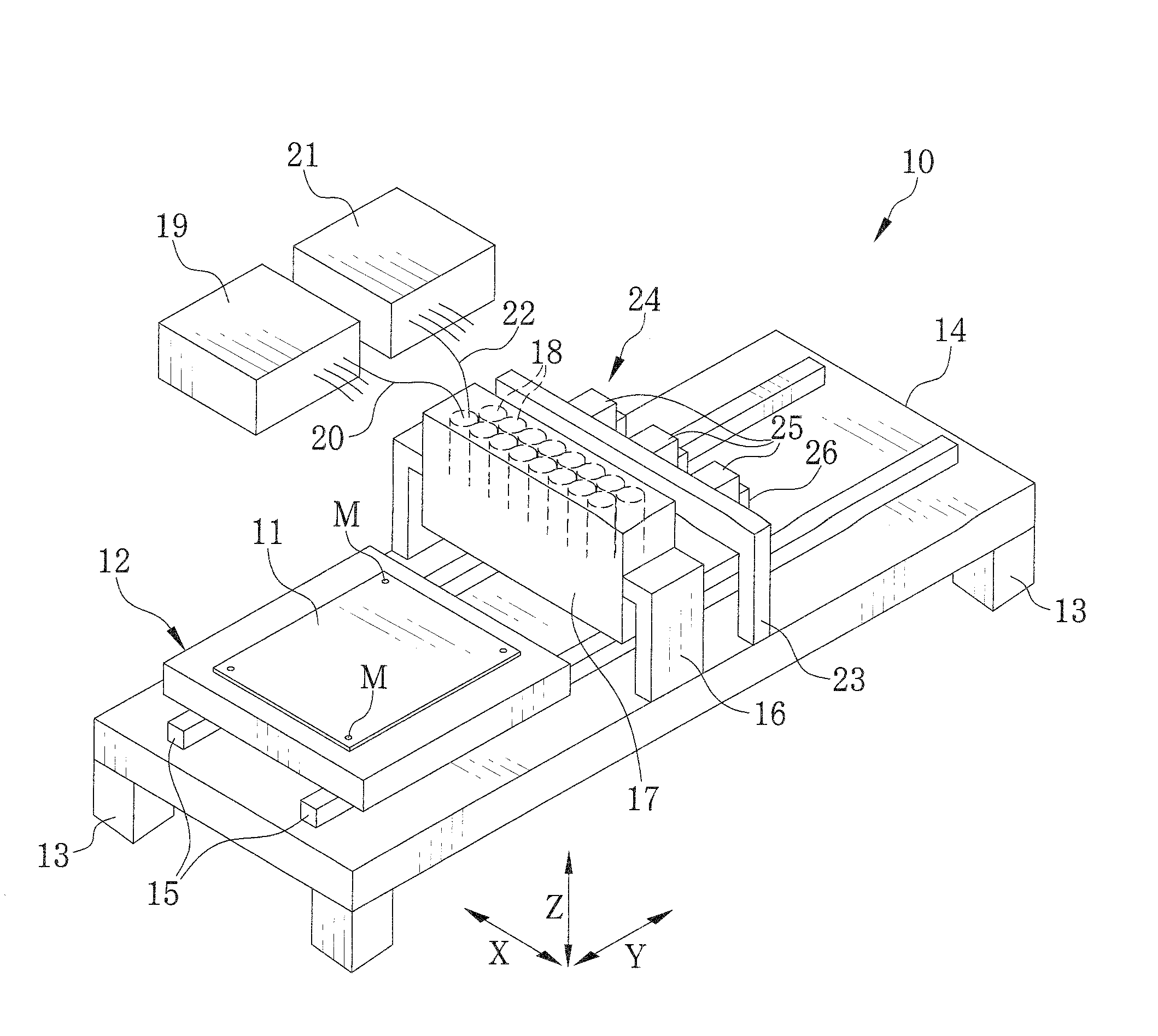
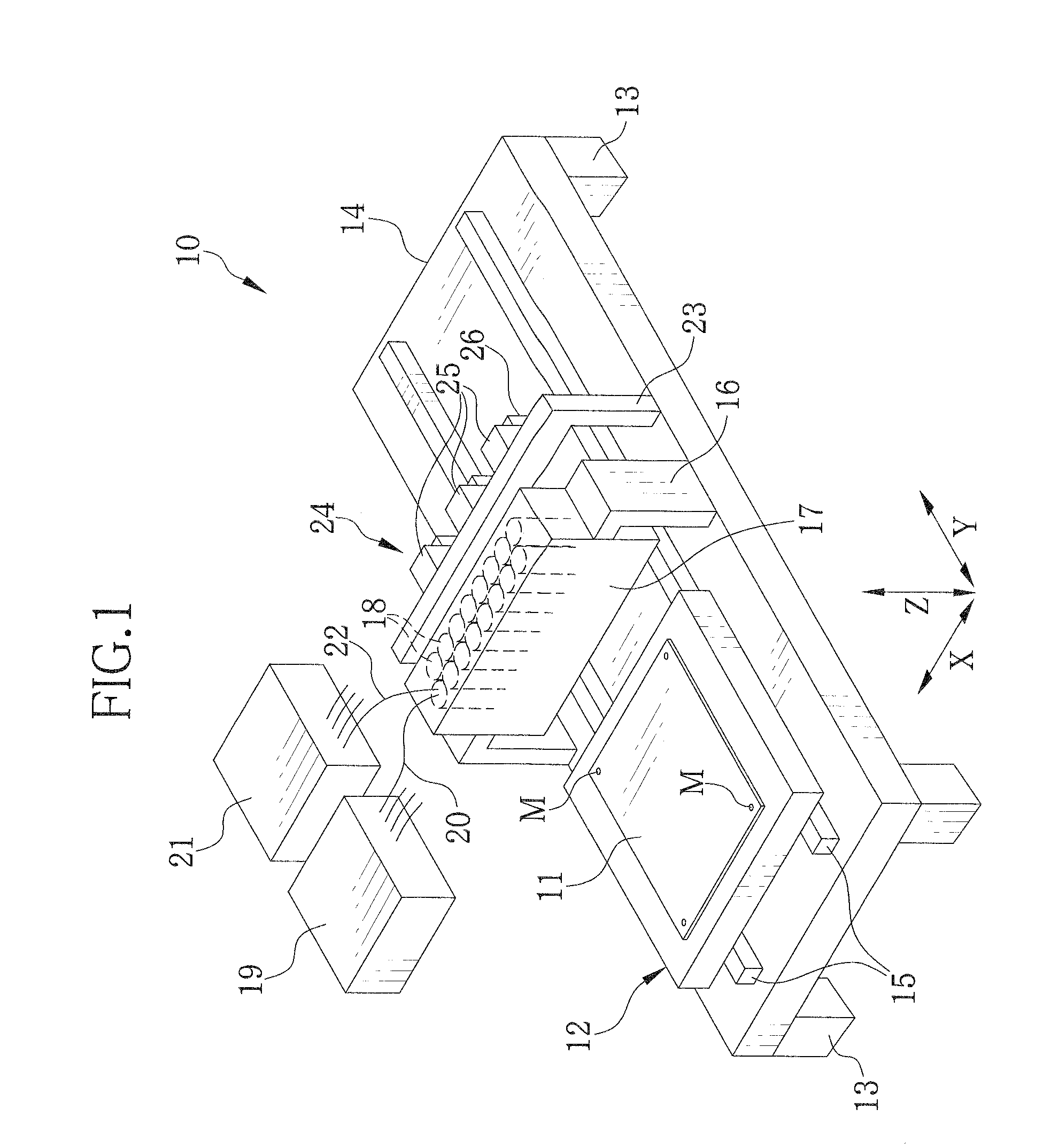
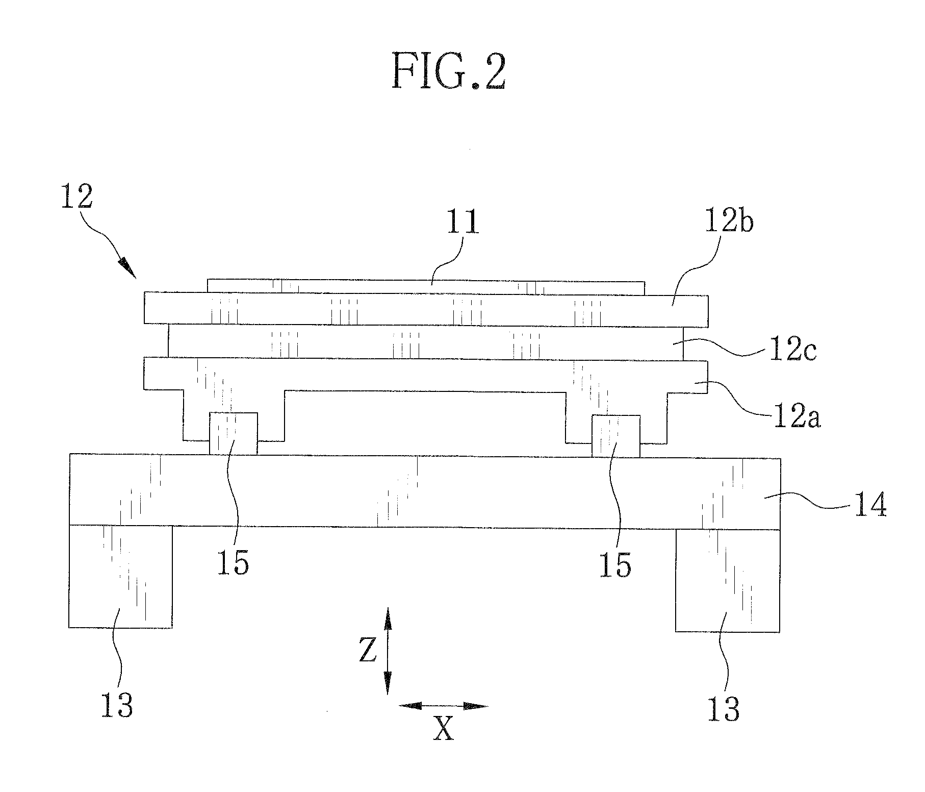
[0039]In FIG. 1, a digital exposure apparatus 10 is provided with a planer stage 12 for carrying a substrate 11 thereon as a target object to form a pattern thereon by optical lithography. The planer stage 12 holds the substrate 11 on its topside by suction. The substrate 11 is one for forming a printed circuit board or a glass substrate for a flat panel display, and a photosensitive material is provided on its topside by coating or adhesion. Also reference marks M are provided on the topside or photosensitive surface of the substrate 11, showing referential points for aligning an exposure position or pattern-forming position on the substrate 11. For example, the reference marks M are formed by embossing thin film and located at each corner of the rectangular substrate 11.

[0040]A base table 14 supports itself on four legs 13, and has a couple of parallel guide rails 15 on its top side. The guide rails 15 extend along a lengthwise direction of the table 14, hereinafter called the Y d...


PUM


Abstract

A digital exposure apparatus for forming a pattern on a topside surface of a substrate has an alignment unit, which detects a position of the substrate from image data obtained through a camera from a reference mark provided on the topside surface of the substrate. The alignment unit further has a Z-direction sensor to measure a fluctuation amount Δ of the topside surface of the substrate from a predetermined focal plane of the camera. Depending upon the measured amount Δ, a set of distortion correction data is selected from or calculated on the basis of previously stored distortion correction data. The image data of the reference mark is corrected with the selected or calculated distortion correction data, so that errors induced by the fluctuation from the focal plane are corrected without adjusting the position of the substrate in the direction of an optical axis of the camera of the alignment unit.

Description

FIELD OF THE INVENTION[0001]The present invention relates to an apparatus and a method of measuring referential position of a substrate by way of reference marks provided on the substrate. The present invention relates also to a pattern-forming apparatus for forming a pattern on a substrate, the pattern-forming apparatus being provided with the referential position measuring apparatus to adjust pattern-forming position on the substrate on the basis of position data measured by the referential position measuring apparatus.BACKGROUND OF THE INVENTION[0002]A digital exposure apparatus, or called a multi-beam exposure apparatus or a beam lithography, is known as a pattern-forming apparatus for forming a pattern on a substrate. The digital exposure apparatus is provided with a spatial light modulator like a digital micromirror device (DMD) in its pattern-forming section, and drives the DMD based on pattern data (digital image signal of a pattern) to modulate light beams so as to form the...

Claims


Application Information

Patent Timeline
Patent Type & Authority Applications(United States)
IPC IPC(8): G03B27/68
CPCG03B27/68G03F9/7088G03F9/7026G03F7/70291
Inventor MORIMOTO, YASUHIKOUEMURA, HIROSHIFUKUI, TAKASHI
Owner FUJIFILM CORP
Why Eureka
Try Eureka