Surgical light provided with a light emission control

a technology of light emission control and surgical light, which is applied in the field of medical technology, can solve the problems of insufficient light field adjusting mechanism, large overall dimensions of lighting devices, and insufficient use of leds in surgical lighting devices, so as to enhance the reliability of lighting devices

Inactive Publication Date: 2008-11-06
ZAO ZAVOD EMA
View PDF4 Cites 12 Cited by
  • Summary
  • Abstract
  • Description
  • Claims
  • Application Information

AI Technical Summary

Benefits of technology

[0019]The arrangement of the main LEDs in a distributed manner on the body of the lighting device and of the additional LEDs between the main LEDs as well as grouping of the LEDs and different spatial orientations of the groups of main and additional LEDs enables electronic adjustment of the light spot diameter, which enhances the reliability of the lighting device.
[0020]The embodiment of the light field adjustment device as a device comprising a control unit, connected to which are the groups of main and additional LEDs by means of controls each of which is connected to the power supply unit, makes it possible to adjust the balance of currents flowing through the groups of main and additional LEDs, thus ensuring redistribution of the luminous flux inside the light field, i.e. enables electronic adjustment of the light field, thus enhancing the performance reliability of the lighting device.

Problems solved by technology

However, until now LEDs have not found broad use in surgical lighting devices, which are required to ensure a shadowless effect and a high illuminating efficiency through high illuminance and uniform distribution of luminous flux across the working zone.
This known lighting device is provided with a light field adjusting mechanism which is not sufficiently effective because of low synchronization of rays, use of extra reflecting surface, and also it has large dimensions.
The known lighting device may only adjust the size of a light spot featuring small depth, this lighting device also has large overall dimensions.
However, light emission control in the known lighting device is performed by mechanical means which ensure the rotation of the light-optical elements relative to each other, reliability of which is reduced as the mechanical parts wear out.

Method used


Image

  • Surgical light provided with a light emission control
  • Surgical light provided with a light emission control
  • Surgical light provided with a light emission control

Examples


Embodiment Construction

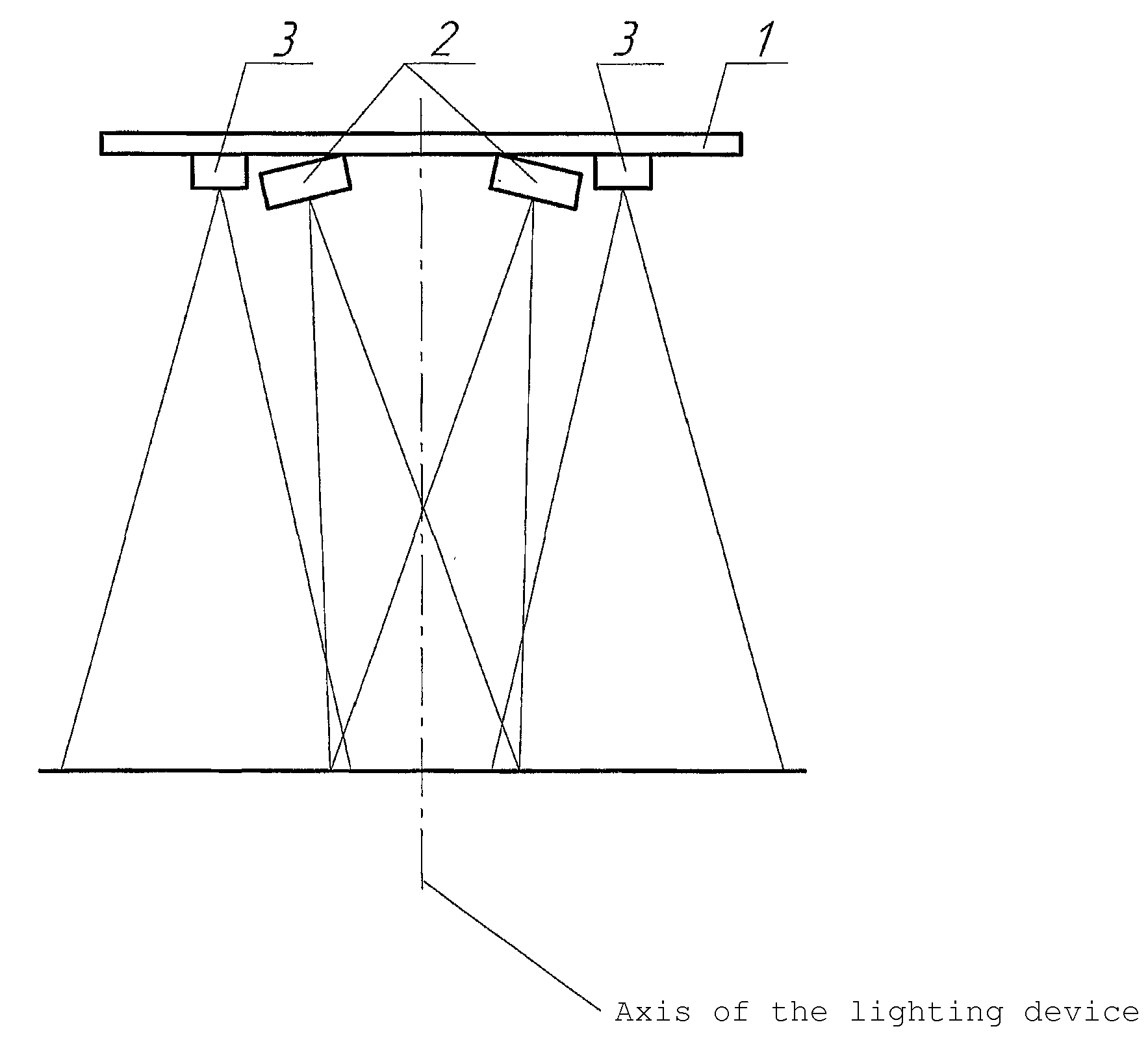
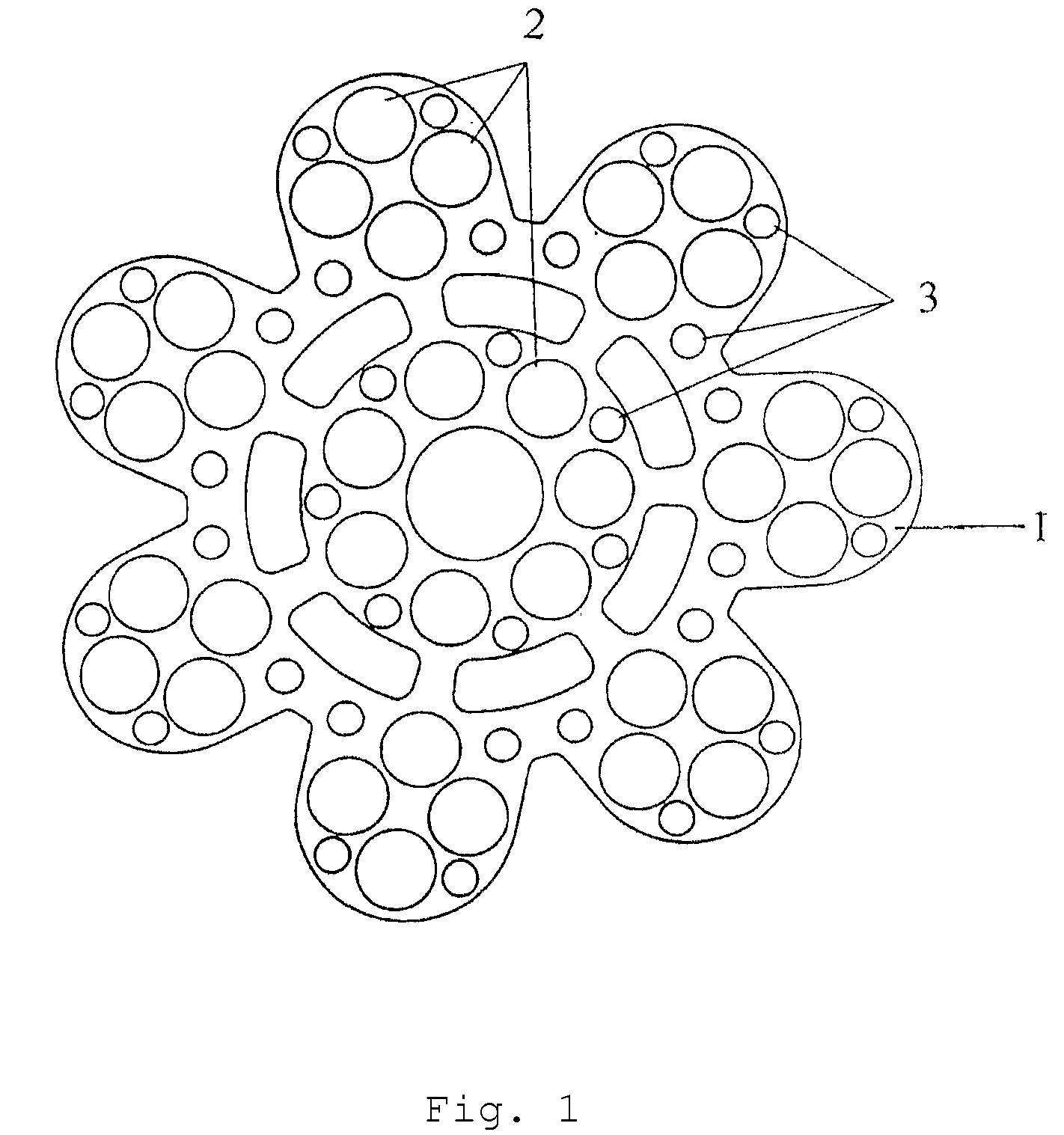
[0028]Attached to body 1 of the lighting device are main LEDs 2 and additional LEDs 3 arranged in groups. Main LEDs 2 have a light beam width equal to 6.5° and are focused so that the optical axes thereof converge at the center of the light spot at a distance of 1 m from the surface. Additional LEDs 3 have a light beam width equal to 100 and are distributed between main LEDs 2 and the optical axes thereof form a concentric ring-shaped light spot around the main light spot with a radius equal to anything from 100 to 200 mm from the center of the spot, which is optimum for surgical lights. The light field control comprises power supply unit 4, control unit 5 with a microcomputer, digital-to-analog converters 6a and 6b, and current generators 7a and 7b.

[0029]As the lighting device is connected to the mains, the power from power supply unit 4 is concurrently fed to the groups of main LEDs 2 and additional LEDs 3. Where a larger area is to be illuminated (in case of extensive wounds) th...


PUM


Abstract

The inventive surgical light comprises a body provided with main light-emitting diodes and additional light-emitting diodes arranged therebetween, which are spaced on said body and fixed thereto, wherein said additional light-emitting diodes are grouped and are characterised in that the spatial orientation thereof differs from the spatial orientation of the main light-emitting diodes. A light field control device comprises a control unit to which the groups of light-emitting diodes are connected by means of adjusters each of which is connected to a power supply unit. The main light-emitting diodes are fixed to the light body in such a way that the optical axes thereof cross the light axis in the center of a light spot. The additional light-emitting diodes are fixed to the light body in such a way that the optical axes thereof form a concentric light spot in the form of a ring around the main light spot.

Description

RELATED APPLICATIONS[0001]This application is a Continuation of PCT application serial number PCT / RU2006 / 000021 filed on Jan. 24, 2006, which is incorporated herein by reference in its entirety.FIELD OF THE INVENTION[0002]This invention relates to medical technology, and more particularly to a lighting device wherein illumination is provided by a plurality of light-emitting diodes with light emission control.BACKGROUND OF THE INVENTION[0003]Since light-emitting diodes came into practice, lighting equipment using lamps composed of light-emitting diodes has displayed special advantages over the existing fluorescent lamps, incandescent lamps and the like, these advantages being their longer service life and lower energy consumption.[0004]Lighting devices with light-emitting diodes (LEDs) used as searchlights or traffic lights are described in detail in the RF patents such as No. 2123633, No. 2151473, No. 2153623, No. 2202731, No. 2227245, No. 2244870, No. 2248499, etc. The purpose ther...

Claims


Application Information

Patent Timeline
Patent Type & Authority Applications(United States)
IPC IPC(8): F21S8/00
CPCA61B19/52A61B19/5202A61B2019/521F21V23/04F21V33/0068F21W2131/205F21Y2101/02Y10S362/80A61B90/36A61B90/30A61B2090/309F21Y2115/10
Inventor KALETIN, ANDREI A.ROSICHINA, OLGA M.TSEPELEV, DMITRY V.OSIPOV, NIKOLAI A.VERSHININ, NIKOLAI F.
Owner ZAO ZAVOD EMA
Why Eureka
Try Eureka