Cavitation-deterring energy-efficient fluid pump system and method of operation

a fluid pump and energy-saving technology, applied in the direction of positive displacement liquid engines, auxilaria, machines/engines, etc., can solve the problems of increased displacement pumps generally suffering from reduced cavitation speeds, application often represents significant challenges, and the arrangement is much more costly and space-consuming. , to achieve the effect of increasing the fluid pressur

Inactive Publication Date: 2008-11-06
METALDYNE BSM
View PDF24 Cites 16 Cited by
  • Summary
  • Abstract
  • Description
  • Claims
  • Application Information

AI Technical Summary

Benefits of technology

[0008]A method of operating a pump system is also provided. The method includes pressurizing a fluid with a positive displacement pump. The fluid is discharged into a discharge passage and a portion of the fluid is flowed from the discharge passage into a valve supply chamber. Pressure is applied to a valve body face. The valve body is moved to open a port in the valve supply chamber. Fluid is ejected into a suction chamber. Finally, the fluid pressure is increased at an inlet to the displacement pump by injecting the fluid across a suction chamber and into a throat passage. The throat passage further receives fluid from a reservoir by means of the suction chamber.
[0009]An internal combustion engine having a balance shaft assembly is also provided. A first positive displacement pump having an inlet and a discharge passage is arranged such that the discharge passage is fluidly coupled with the balance shaft assembly. A jet pump valve having a variable nozzle opening area is provided where the variable nozzle opening is fluidly coupled between the discharge and the inlet passage. The jet pump valve includes means for changing the area of the variable nozzle opening in direct response to changes in fluid pressure in the discharge passage. The jet pump valve further includes an urging member arranged to bias a member to close the variable nozzle opening. A suction chamber is arranged in the jet pump valve adjacent the variable nozzle opening to receive fluid from the variable nozzle opening and a fluid reservoir. The jet pump valve further includes a throat passage coupled to the suction chamber. The throat passage is fluidly coupled to receive fluid from the reservoir and the variable valve opening and transfer the received fluid to the inlet passage.

Problems solved by technology

However, such applications often represent significant challenge when an operating speed range that is often greater than an order of magnitude in breadth is combined with a requirement for copious low speed flow volume.
This is due to increased-displacement pumps generally suffering from reduced cavitation speeds, those where pump filling becomes challenged for lack of sufficient inlet passage pressure.
This arrangement is much more costly and space-consumptive than necessary to achieve the desired functionality of optimized energy efficiencies and cavitation speeds in fluid pump systems that for avoidance of cost, complexity, or packaging space claim require positive displacement pumps to function over a wide range of speeds.
Other prior art adjustable nozzle jet pumps having normally non-passing pressure control valve functionality similarly define much more costly and complex structures than are necessary for the purpose of achieving the above-cited desired functionality.

Method used


Image

  • Cavitation-deterring energy-efficient fluid pump system and method of operation
  • Cavitation-deterring energy-efficient fluid pump system and method of operation
  • Cavitation-deterring energy-efficient fluid pump system and method of operation

Examples


Embodiment Construction

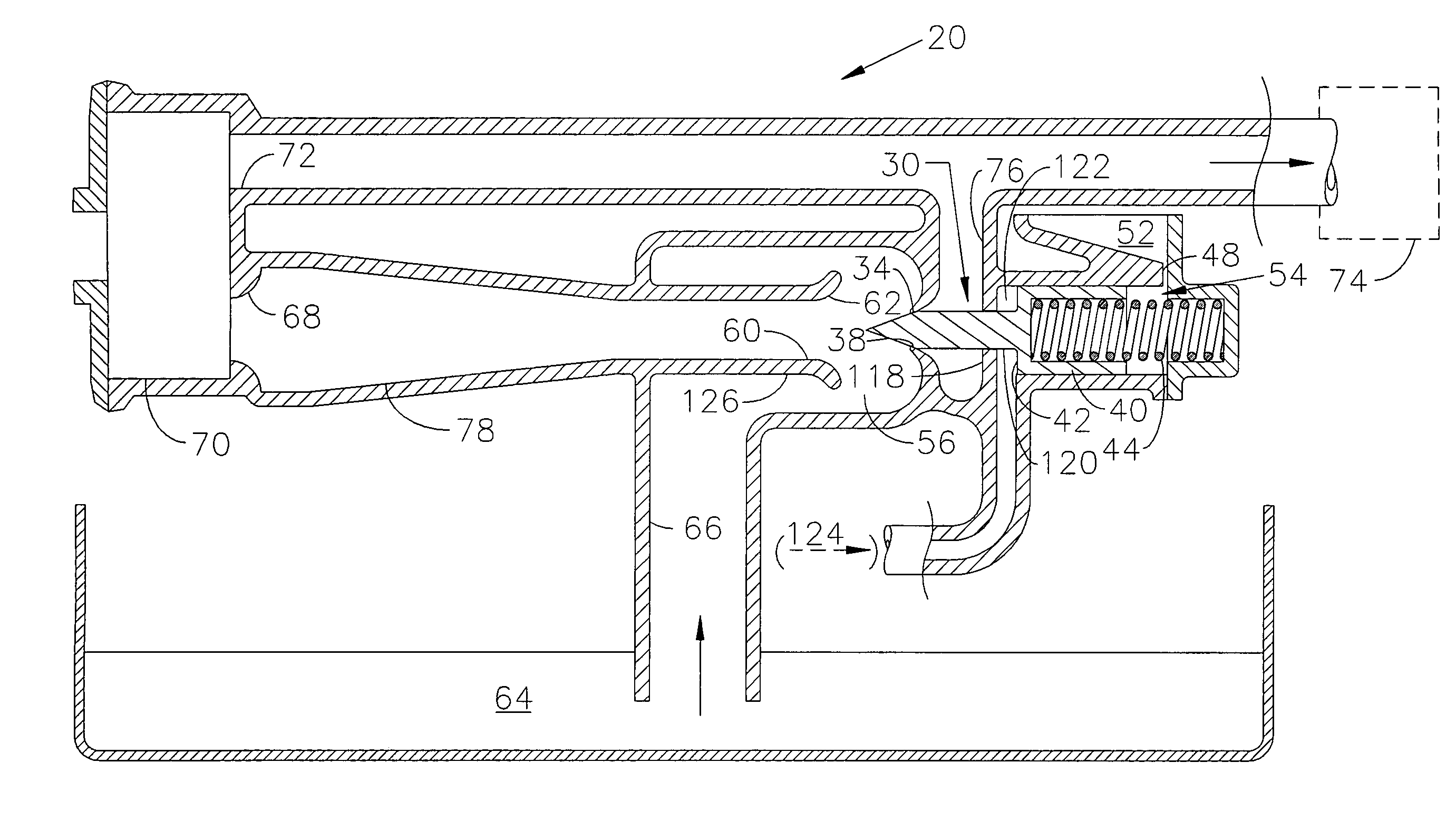
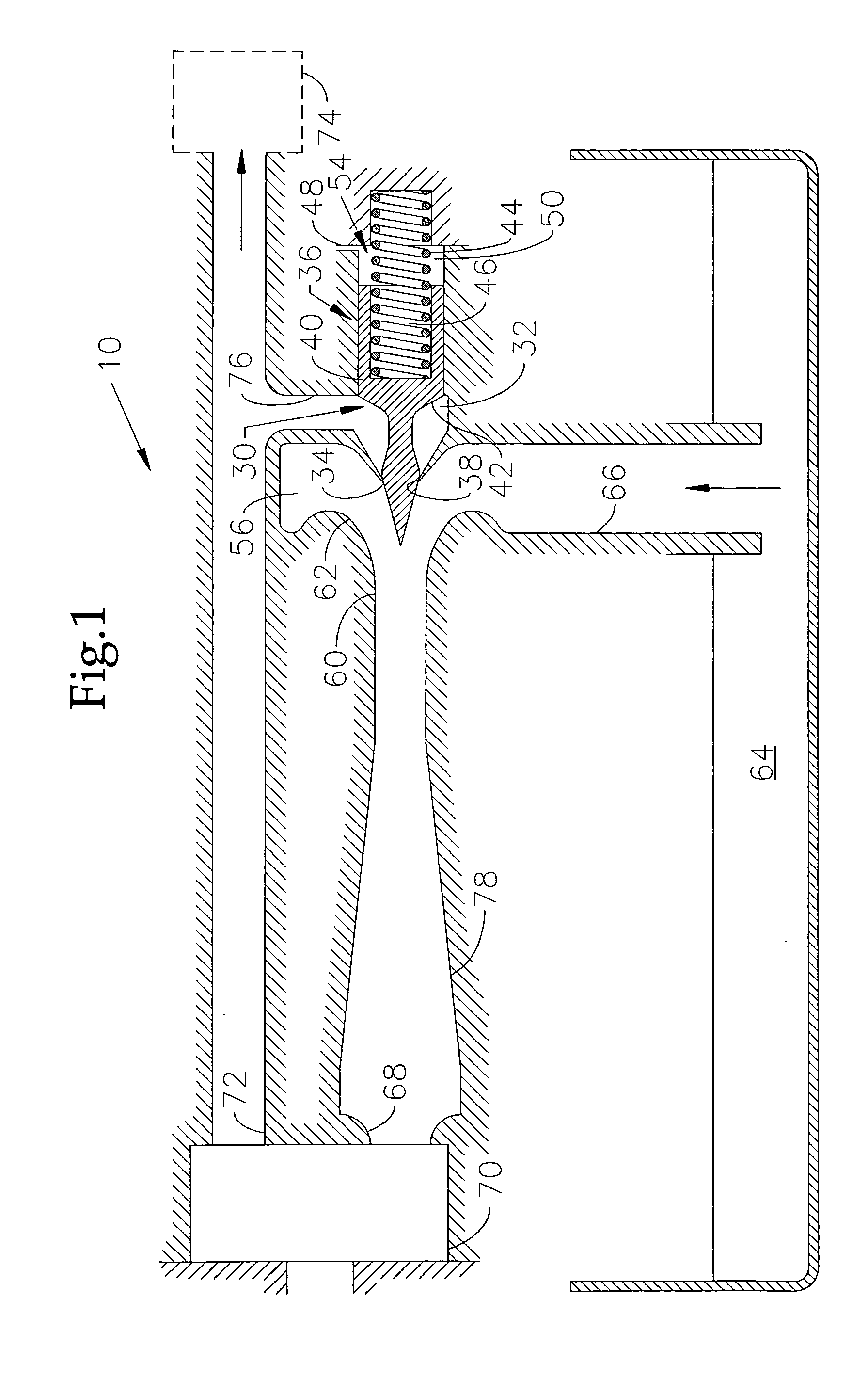
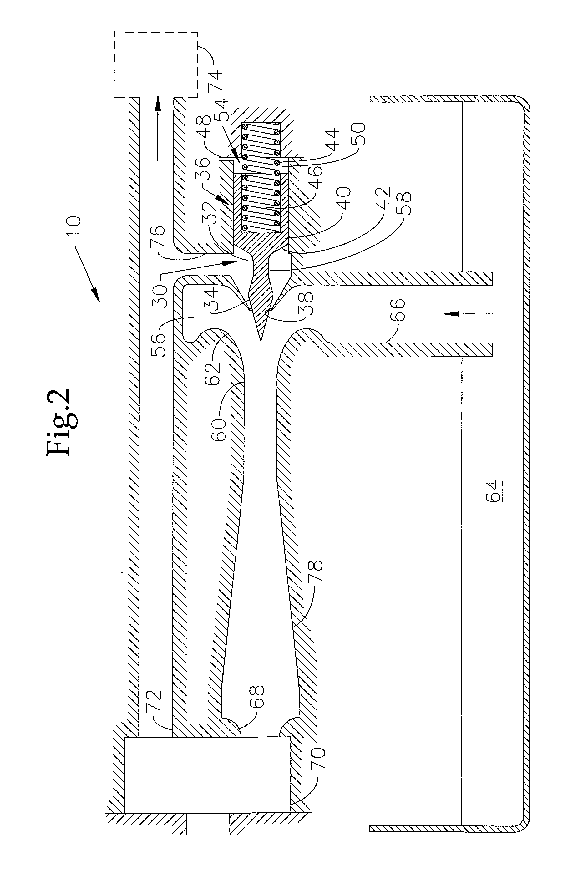
[0029]Adjustable nozzle jet pumps are known for substantially extended efficiency range in comparison with fixed nozzle area jet pumps. In the exemplary embodiment, a consistently high velocity of nozzle exit flow enables an automatically-adjusted variable nozzle area jet pump to provide this performance advantage more or less continually in the case of variable operating conditions. Substantial further efficiency range advantages are gained over fixed area ratio jet pump-assisted positive displacement pumping systems by means of the exemplary embodiment's low cost, compact integration of normally non-passing pressure control valve functionality with an adjustable nozzle-type jet pump.

[0030]The exemplary embodiment utilizes this simple normally non-passing pressure-controlling adjustable nozzle jet pump valve (hereafter referred to as a “Jet Pump Valve” or “JPV”) to captively recirculate unused flow volumes back to a positive displacement pump's inlet with pressure boost (or reducti...


PUM


Abstract

A variable nozzle area jet pump is provided having a nozzle-sealing member resiliently urged to form a sealing closure. The sealing member is part of a normally non-passing pressure control valve that recirculates excess fluid back to the inlet of a positive displacement fluid pump. The fluid is recirculated with elevated pressure after a threshold fluid pressure is exceeded. The disclosed system provides for energy conservation and pump cavitation speed increase. The system may be integrated with an engine balance shaft module so as to provide low cost robustness to low speed gear noise emissions by application of the oil pump's drive torque to at lease one gearset.

Description

CROSS REFERENCE TO RELATED APPLICATION[0001]This application claims benefit of U.S. Provisional Application Ser. No. 60 / 927,484 filed May 3, 2007, and entitled “Energy Efficient Fluid Pump System.” which is incorporated by reference herein in its entirety.FIELD OF ART[0002]The present invention relates generally to a fluid pump system for an engine or other system, and more particularly, to the provision of low cost increases in the cavitation speeds of positive displacement fluid pumps, concurrent with useful power consumption reductions over a wide range of operational speeds, in applications offering limited packaging space.BACKGROUND[0003]The use of an adjustable nozzle area jet pump having normally non-passing pressure control valve functionality to conserve energy by delivering pressurized recirculation flow back to the inlet of a positive displacement fluid pump under widely varying load conditions is known in the art. The use of a positive displacement pump to reduce the tim...

Claims


Application Information

Patent Timeline
Patent Type & Authority Applications(United States)
IPC IPC(8): F04F5/44F04F5/50F01M1/02
CPCF04B23/12F04C11/005F04C15/062F04F5/461F04F5/54F04F5/46
Inventor KILLION, DAVID L.
Owner METALDYNE BSM
Why Eureka
Try Eureka