Device for carrying out chemical or biological reactions
a technology for biological reactions and devices, applied in the field of devices for carrying out chemical or biological reactions, can solve the problems of inability to vary parameters, increase the probability of errors, accelerate the addition of bases,
- Summary
- Abstract
- Description
- Claims
- Application Information
AI Technical Summary
Benefits of technology
Problems solved by technology
Method used
Image
Examples
first embodiment
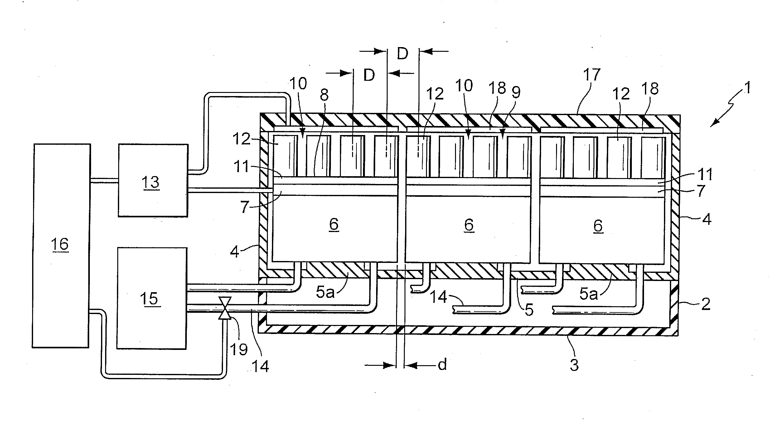
[0058]FIG. 1 shows the device 1 according to the invention for carrying out chemical or biological reactions in a schematic sectional view.
[0059]The device has a housing 2 with a bottom 3 and side walls 4. Located just above and parallel to the bottom 3 is an intermediate wall 5, on which are formed several bases 5a. In the embodiment shown in FIG. 1, a total of six bases 5a are provided, arranged in two rows of three bases 5a each.
[0060]Mounted on each of the bases 5a is a heat exchanger 6, a Peltier element 7 and a segment 8 of a reaction vessel receiving element 9. The heat exchanger 6 is part of a cooling device and the Peltier element 7 is part of a combined heating and cooling device. The elements (heat exchanger, Peltier element, segment) mounted on the bases 5a are bonded by an adhesive resin with good heat conducting properties, so that good heat transfer is realized between these elements, and the elements are also firmly connected to a segment element 10. The device has a...
second embodiment
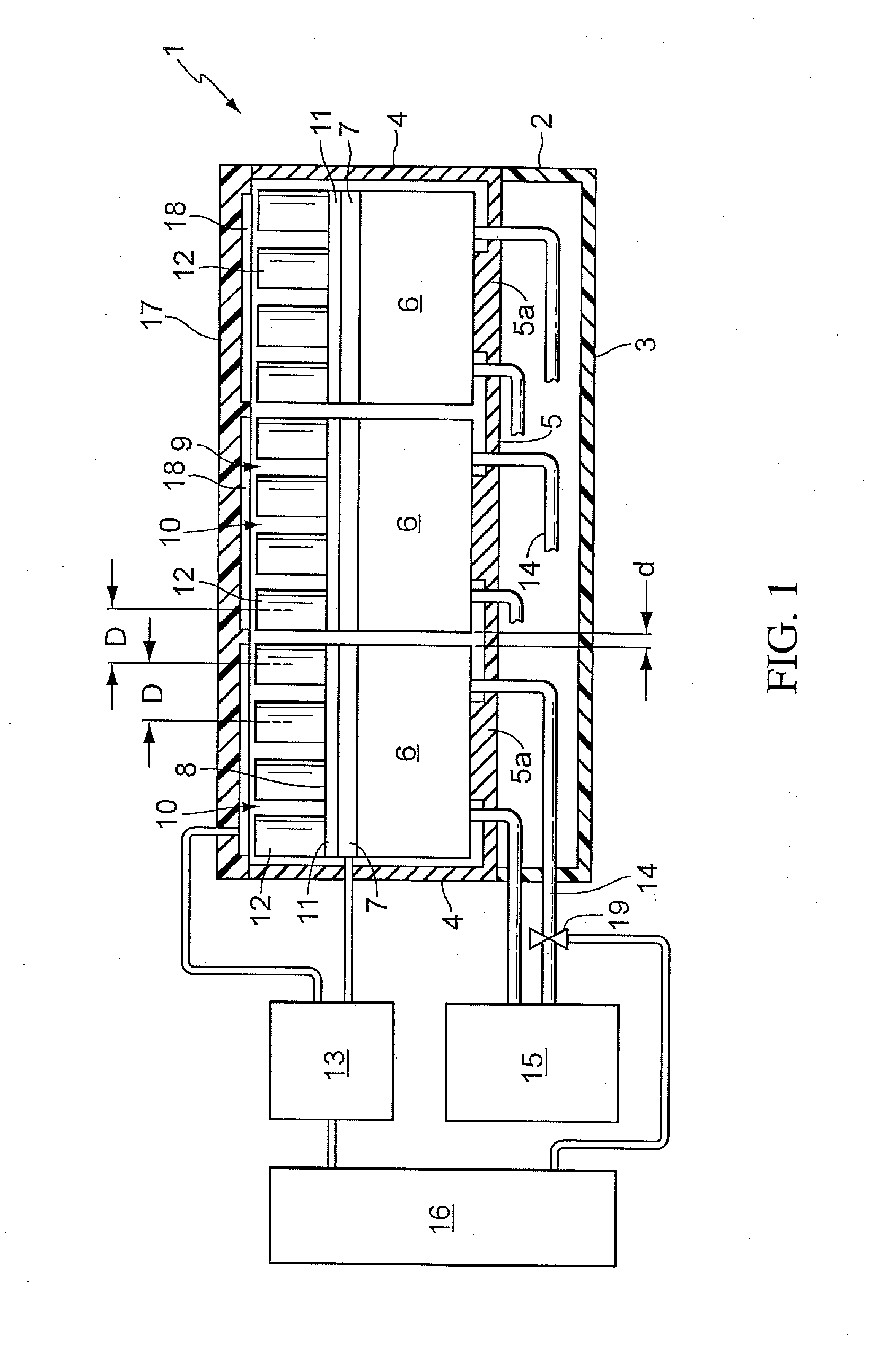
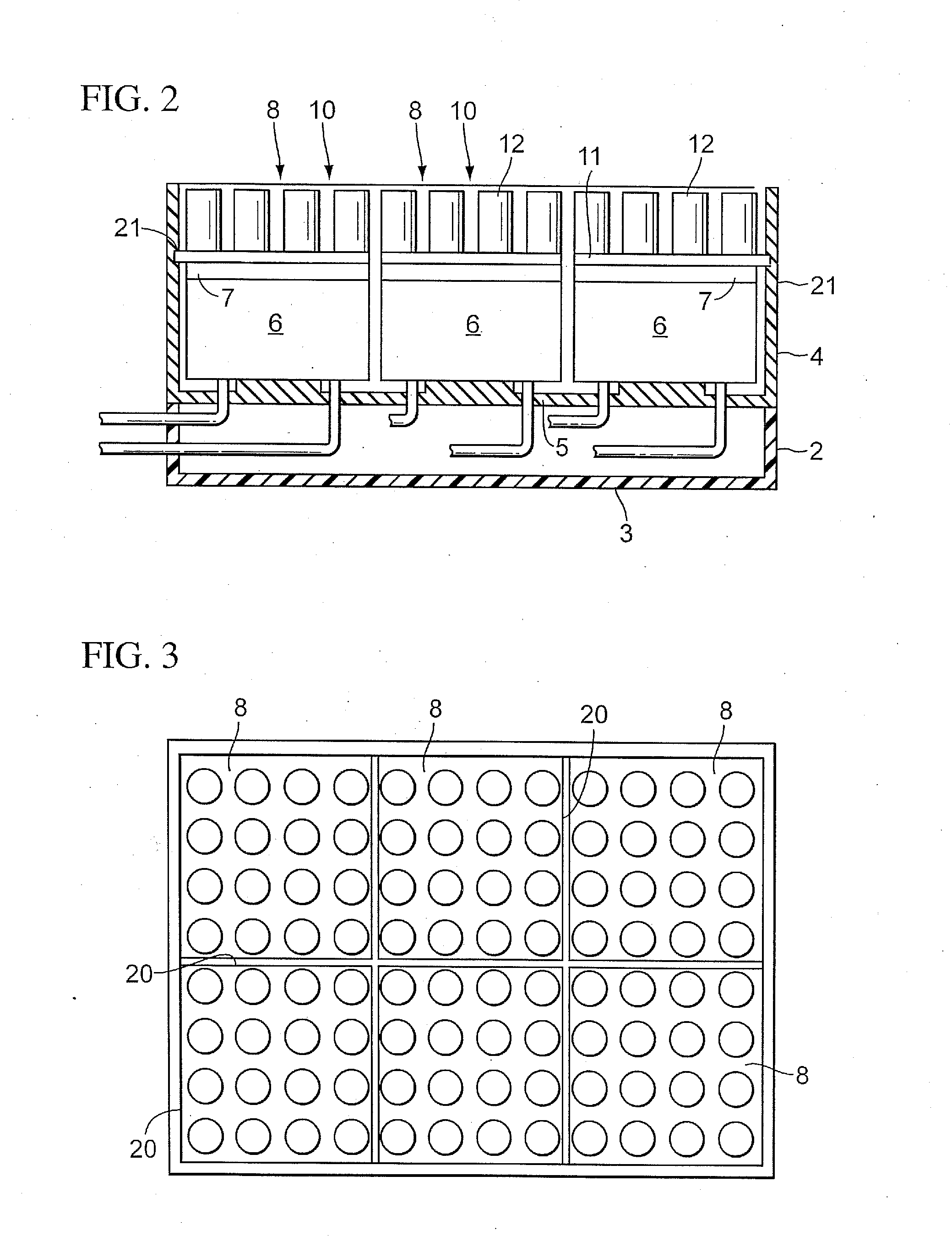
[0076]the device according to the invention is shown in FIGS. 2 and 3. The basic design corresponds to that of FIG. 1, so that identical parts have been given the same reference number.
[0077]The second embodiment differs from the first embodiment by virtue of the fact that the side edges 20 of the segments 8 adjacent to the side walls 4 of the housing 2 engage in a slot 21 running round the inner face of the side walls 4, and are fixed therein for example by bonding. By this means the individual segment elements 10 are fixed in space, thereby ensuring that despite the form of the gaps between the segment elements 10, all reaction vessel holders 12 are arranged in the pattern of the reaction vessels of a microtiter plate. The side walls 4 of the housing 2 are made of a non heat conducting material. This embodiment may also be modified such that the slot 21 is introduced in a frame formed separately from the housing 2. The frame and the segments inserted in it form a part which may be...
third embodiment
[0078]A third embodiment is shown schematically in FIGS. 4 and 5. In this embodiment, ties 22 of non heat conducting material are located somewhat below the base plates 11 of the segments 8 in the areas between the segment elements 10 and between the segment elements 10 and the side walls 4 of the housing 2. On the side edges 20 of the segments 8 and of the base plates 11 respectively are formed hook elements 23 which are bent downwards. These hook elements 23 engage in corresponding recesses of the ties 22 (FIG. 5), thereby fixing the segments 8 in their position. The hook elements 23 of adjacent segments 8 are offset relative to one another. The ties 22 thus form a grid, into each of the openings of which a segment 8 may be inserted.
[0079]This type of position fixing is very advantageous since the boundary areas between the segments 8 and the ties 22 are very small, so that heat transfer via the ties 22 is correspondingly low. Moreover this arrangement is easy to realise even in t...
PUM
| Property | Measurement | Unit |
|---|---|---|
| elongation temperature | aaaaa | aaaaa |
| temperature | aaaaa | aaaaa |
| temperature | aaaaa | aaaaa |
Abstract
Description
Claims
Application Information
 - R&D
- Intellectual Property
- Life Sciences
- Materials
- Tech Scout
- Unparalleled Data Quality
- Higher Quality Content
- 60% Fewer Hallucinations
Browse by: Latest US Patents, China's latest patents, Technical Efficacy Thesaurus, Application Domain, Technology Topic, Popular Technical Reports.
© 2025 PatSnap. All rights reserved.Legal|Privacy policy|Modern Slavery Act Transparency Statement|Sitemap|About US| Contact US: help@patsnap.com


