
Method for producing fibre reinforced laminated structures

a technology of fibre reinforced laminates and fibre reinforced sheets, which is applied in the field of fibre reinforced laminate production, can solve the problems wrinkles in the laminate structure, etc., and achieve the effects of high permeability, reduced risk of delamination and air pockets, and increased wetting

Inactive Publication Date: 2008-11-13
SIEMENS AG
View PDF20 Cites 49 Cited by
  • Summary
  • Abstract
  • Description
  • Claims
  • Application Information

AI Technical Summary

Benefits of technology

[0017]By using such flow enhancing layers it is possible to ensure sufficient wetting of all fibre reinforcement layers even in thick layer stacks. Therefore, the risk of delamination and air pockets, which would lead to wrinkles, is highly reduced. Moreover, the laminated structure can be made of a continuous structure without points where different structures abut each other.
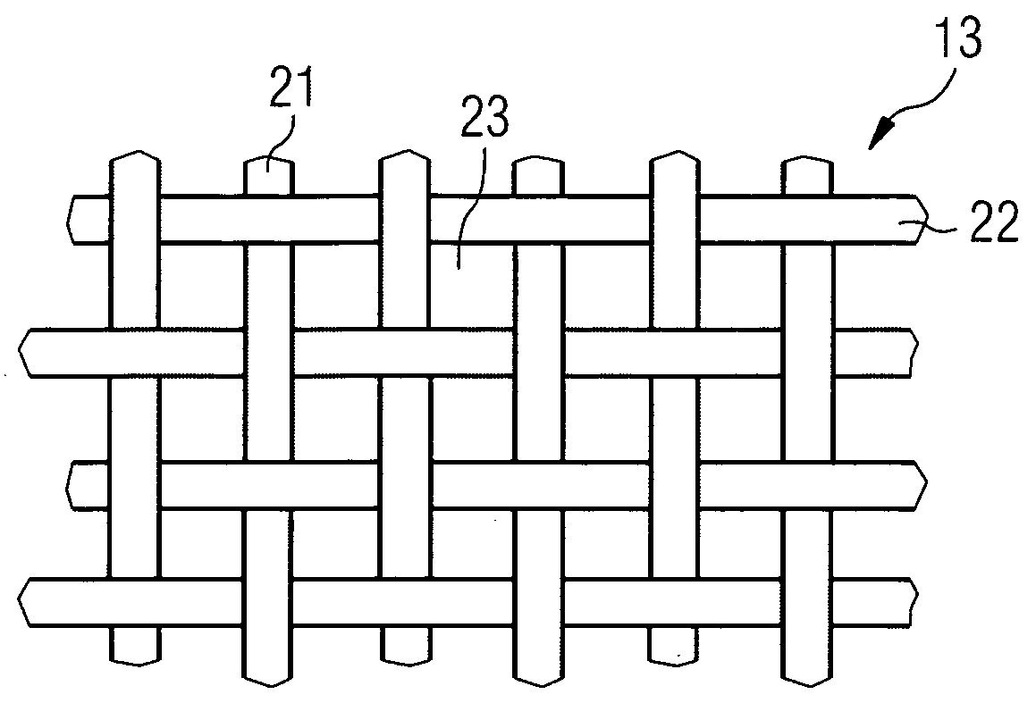
[0018]As a flow-enhancing layer, a layer may be used which is made of a layer material having a higher permeability with respect to the polymer than a layer made of the material of the fibre reinforcement layers and having the same thickness as the flow-enhancing layer. For example, the higher permeability could be achieved by a lower fibre density of the layer material as compared to the material of the fibre reinforcement layers. However, it is even more advantageous if a meshed or woven layer or a perforated layer is used as a flow-enhancing layer. In this case, the flow-enhancing layer may be made from the same material as the fibre reinforcement layers. However, the meshed or woven layer or the perforated layer may also be implemented as a pre-cured solid layer. This ensures that its flow-enhancing property is maintained even if pressure is applied to the layers during infusion of the polymer or a vacuum is present during infusion. If the flow-enhancing layer has too high a compressibility, there could be a risk of reducing its flow-enhancing properties too much when applying pressure or vacuum.
[0019]Although the same material may be used for the flow-enhancing layers as is used for the fibre reinforcement layers, it may be advantageous if a different material is used for forming the flow-enhancing layers. This offers the possibility of providing a desired stiffness ratio of the flow-enhancing layers to the fibre reinforcement layers after curing the resin.
[0020]In addition, in particular the perforated layers may be corrugated to increase the space available for polymer flow.
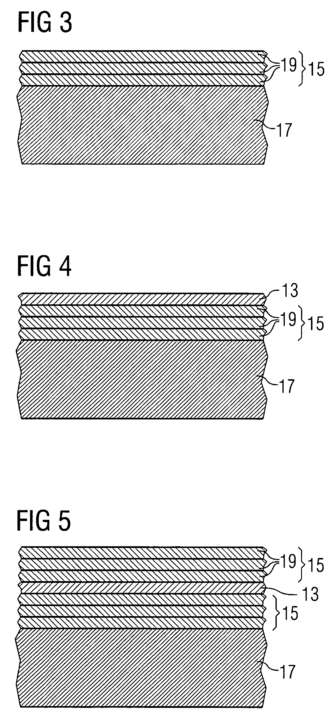
[0021]In particular, if thick fibre reinforced laminated structures are to be produced, one may create a stack comprising a number of fibre reinforcement layers and then lay at least one flow-enhancing layer on top of the stack when layering the number of dry fibre reinforcement layers. This offers the possibility of forming stacks of fibre reinforcement layers without a flow-enhancing layer up to a thickness for which sufficient wetting can be ensured without a flow-enhancing layer so that the overall number of flow-enhancing layers can be kept small. In particular, a number of stacks and a number of flow-enhancing layers can be layered such that stacks and flow-enhancing layers alternate. The flow-enhancing layers then ensure that a sufficient amount of polymer can flow between different stacks of fibre reinforcement layers for sufficiently wetting all fibre reinforcement layers of the stacks.

Problems solved by technology

If the wetting is insufficient, this may lead to delamination and air pockets within the laminate structure and, as a consequence, to wrinkles in the laminate structure which constitute weak points of the structure.
This deficiency is in particular an issue in case of thick fibre reinforced laminated structures such as, e.g. spar caps of wind turbine rotor blades.

Method used


Image

  • Method for producing fibre reinforced laminated structures
  • Method for producing fibre reinforced laminated structures
  • Method for producing fibre reinforced laminated structures

Examples


Embodiment Construction

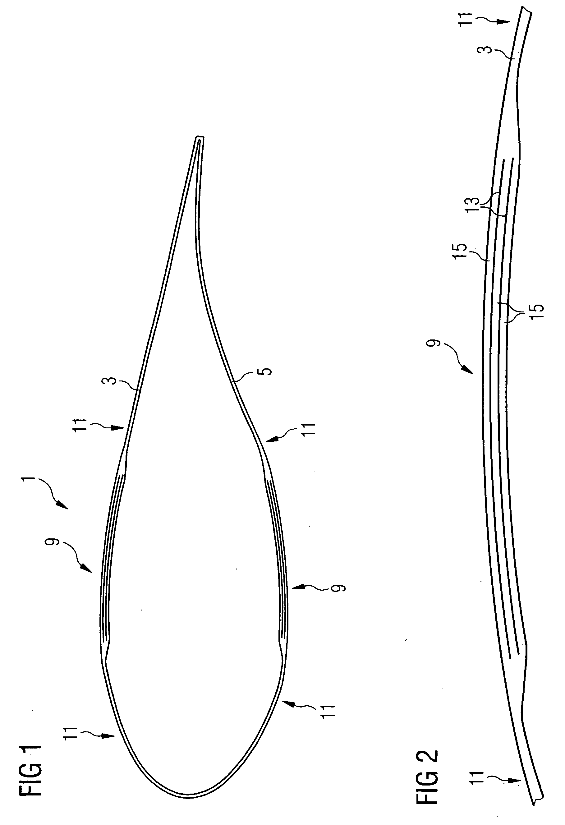
[0034]FIG. 1 is a schematic view of the cross-section of a laminated wind turbine rotor blade 1. The rotor blade 1 is made of an upper shell 3 and a lower shell 5 each comprising a thickened section 9 and non thickened sections 11. The upper and lower shells 3, 5 comprise a number of fibre reinforcement layers which are not individually shown in the figure. In the thickened section 9 the number of reinforcement layers is increased with respect to the non-thickened sections 11.

[0035]The thickened section 9 of the upper shell 3 is shown in more detail in FIG. 2. In the thickened section 9, flow-enhancing layers 13 are present between stacks of fibre reinforcement layers 15. The fibre reinforcement layers 15, as well as the flow-enhancing layers 13, are embedded in a resin matrix which has been formed by resin infusion and subsequent curing of the resin. During the infusion process the flow-enhancing layers 13 layered between neighbouring stacks 15 of the fibre reinforcement layers ens...


PUM

PropertyMeasurementUnit
Thicknessaaaaaaaaaa
Flow rateaaaaaaaaaa
Permeabilityaaaaaaaaaa

Abstract

There is described a method of producing fibre reinforced laminated structures by layering a number of dry fibre reinforcement layers by placing them on top of each other in a mould, infusing a curable viscous or liquid polymer into the mould after the fibre reinforcement layers have been layered in the mould and curing the polymer, wherein a flow enhancing layer for enhancing the polymer flow during infusion of the polymer is placed between two fibre reinforcement layers when layering the number of dry fibre reinforcement layers and wherein a pre-cured solid layer is used as the flow enhancing layer.

Description

CROSS REFERENCE TO RELATED APPLICATIONS[0001]This application claims priority of European Patent Office application No. 07009187.1 EP filed May 7, 2007, which is incorporated by reference herein in its entirety.FIELD OF INVENTION[0002]The present invention relates to a method of producing fibre reinforced laminated structures, such as wind turbine rotor blades, by placing a number of dry fibre reinforcement layers on top of each other in a mould, injecting a curable viscose or liquid polymer into the mould after the fibre reinforcement layers have been placed in the mould and curing the polymer.BACKGROUND OF INVENTION[0003]In such methods of producing fibre reinforced laminated structures it is of importance to ensure sufficient wetting of the dry reinforcement layers after they have been placed in the mould. If the wetting is insufficient, this may lead to delamination and air pockets within the laminate structure and, as a consequence, to wrinkles in the laminate structure which c...

Claims


Application Information

Patent Timeline
IPC IPC(8): B29C47/04
CPCB29C70/342B29C70/547B29L2009/00B29L2031/08B29L2031/085Y02P70/50
Inventor STIESDAL, HENRIK
Owner SIEMENS AG
Learn More