
Electric power steering apparatus

a technology of electric power steering and steering wheel, which is applied in the direction of electric generator control, dynamo-electric converter control, dynamo-electric gear control, etc., can solve the problems of vibration and stress applied to the steerable wheels in the steering system, and achieve the effect of suppressing rattling noise and suppressing rattling nois

Inactive Publication Date: 2008-11-13
JTEKT CORP
View PDF3 Cites 30 Cited by
  • Summary
  • Abstract
  • Description
  • Claims
  • Application Information

AI Technical Summary

Benefits of technology

The present invention provides an electric power steering apparatus that reduces rattling noise caused by stress applied to steerable wheels. The apparatus includes a steering force assist device, control means, and a speed reducing mechanism. The control means controls the actuation of the steering force assist device to suppress rattling noise generated in the meshed part of the first and second gears based on a frequency analysis of a vibration generated in the steering system. The technical effect of this invention is to improve the steering performance and comfort of the vehicle by reducing rattling noise and improving the overall driving experience.

Problems solved by technology

Thus, the rattling noise is generated in the speed reducing mechanism.
Furthermore, the stress applied to the steerable wheels remains in the steering system as vibration.

Method used


Image

  • Electric power steering apparatus
  • Electric power steering apparatus
  • Electric power steering apparatus

Examples


first embodiment

[0026]A column type electric power steering apparatus (EPS) 1 according to a first embodiment of the present invention will now be described with reference to the accompanying drawings.

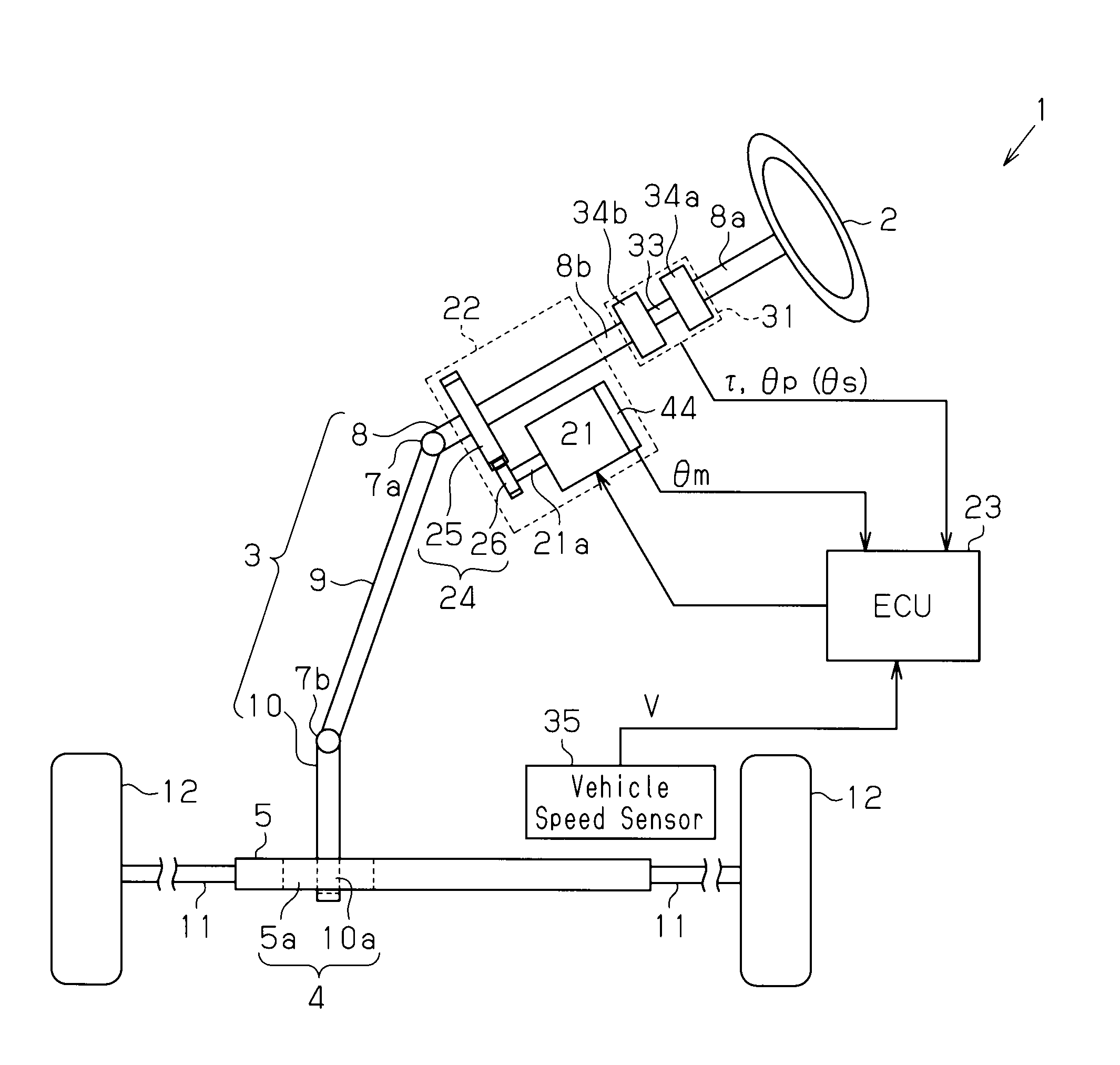
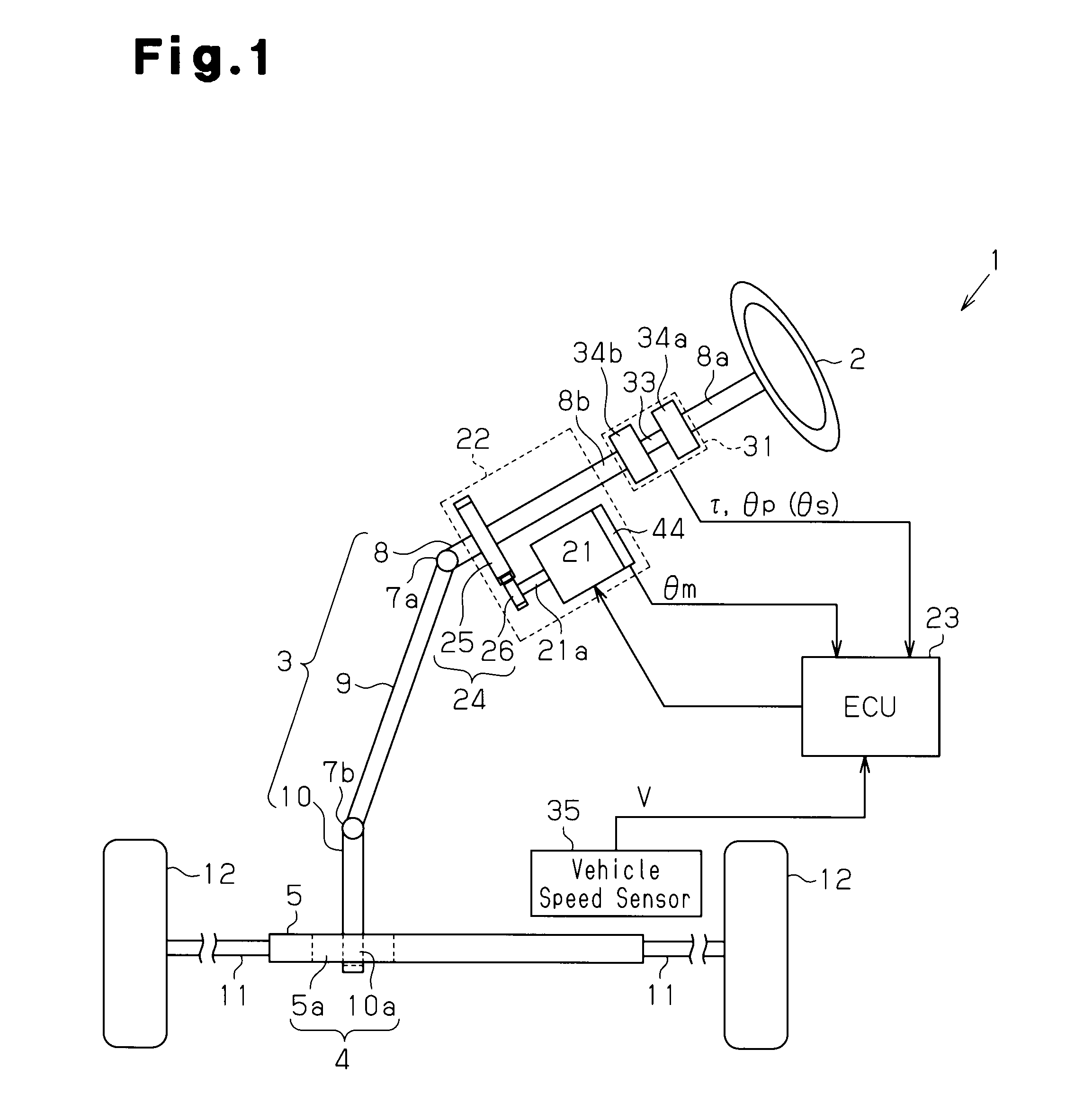
[0027]As shown in FIG. 1, in the electric power steering apparatus (EPS) 1, a steering wheel 2 is fixed to a steering shaft 3. The steering shaft 3 is coupled to a rack shaft 5 via a rack-and-pinion mechanism 4. Rotation of the steering shaft 3 accompanying a steering operation is converted into a reciprocating linear motion of the rack shaft 5 by the rack-and-pinion mechanism 4. Specifically, the steering shaft 3 is configured by a column shaft 8, an intermediate shaft 9, and a pinion shaft 10. The column shaft 8 and the intermediate shaft 9 are coupled to each other via a universal joint 7a, and the intermediate shaft 9 and the pinion shaft 10 are coupled to each other via a universal joint 7b. The rack-and-pinion mechanism 4 is constituted by pinion teeth 10a formed at the lower end of the pinion s...

second embodiment

[0067]A description will be given below of a second embodiment of the present invention with reference to the accompanying drawings.

[0068]A main difference between the present embodiment and the first embodiment lies only in the control of suppressing the rattling noise. To facilitate illustration, like or the same reference numerals are given to those components that are like or the same as the corresponding components of the first embodiment, and the explanations are omitted.

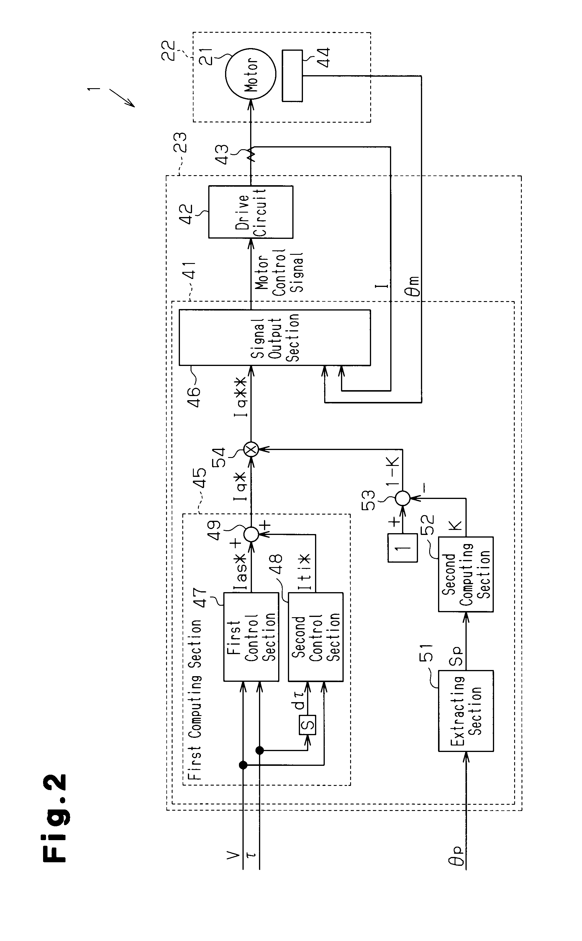
[0069]As shown in FIG. 6, a microcomputer 61 includes frequency removing means, which is a notch filter 70 in the second embodiment. The notch filter 70 removes, from an input signal, the frequency component corresponding to the vibration that increases the rattling noise generated in the speed reducing mechanism 24. The first computing section 45 of the microcomputer 61 receives a steering torque τ′ that has passed through the notch filter 70.

[0070]In other words, the notch filter 70 removes, from the steerin...


PUM


Abstract

A microcomputer is provided with an extracting section capable of extracting a specific frequency component from an input signal. The extracting section extracts, from a pinion angle corresponding to a signal indicating the state of a steering system, a frequency component corresponding to a vibration that increases generation of a rattling noise in a speed reducing mechanism. The extracting section outputs an effective value of the extracted frequency component as a power spectrum. If the power spectrum output from the extracting section is equal to or more than a predetermined threshold value, the microcomputer outputs a motor control signal to reduce the assist force generated by the EPS actuator.

Description

[0001]This application is based on and claims priority from Japanese Patent Application No. 2007-122375 filed on May 7, 2007, the entire contents of which are incorporated herein by reference.BACKGROUND OF THE INVENTION[0002]The present invention relates to an electric power steering apparatus.[0003]Conventionally, an electric power steering apparatus (EPS) provided with a motor as a driving source applies a motor torque as an assist force to a steering system by rotating a steering shaft. In general, in such an EPS, the motor is coupled to the steering shaft via a speed reducing mechanism (for example, a worm and wheel mechanism), which includes first and second gears meshed with each other. For example, according to the configuration disclosed in Japanese Laid-Open Patent Publication No. 2004-291718, rotation of the motor is reduced by the speed reducing mechanism, and is transmitted to the steering shaft.[0004]Most EPS apparatuses include a torque sensor 93 as shown in FIG. 16. T...

Claims


Application Information

Patent Timeline
Patent Type & Authority Applications(United States)
IPC IPC(8): B62D5/04B62D6/00B62D113/00B62D119/00B62D137/00F16H57/12H02P21/00H02P23/24H02P27/04
CPCB62D5/0463B62D5/0472
Inventor NISHIMURA, AKIHIKO
Owner JTEKT CORP
Learn More