Fluid Transfer Assembly

Active Publication Date: 2008-11-13
DOW SILICONES CORP
View PDF44 Cites 37 Cited by
  • Summary
  • Abstract
  • Description
  • Claims
  • Application Information

AI Technical Summary

Benefits of technology

[0011]Accordingly, the subject invention sets forth a fluid transfer assembly with a manifold and tubes each being formed of silicone. The manifold has a particular advantageous structure which allows the tubes to be inserted within the connector portions of the manifold. Once assembled,

Problems solved by technology

Other materials, such as polyvinyl chloride (PVC), are typically not used for transfer assemblies in pharmaceutical manufacturing as these materials can leach into the medicinal substances which will pollute the substance and destroy the purpose of the transfer assembly.
One drawback to the prior art connectors and tubes discussed above relates to a gap or void that is created between the tubes and the connector once the tubes are mounted to the connector.
In addition, there is a potential that the tubes could become detached f

Method used


Image

  • Fluid Transfer Assembly
  • Fluid Transfer Assembly
  • Fluid Transfer Assembly

Examples


Embodiment Construction

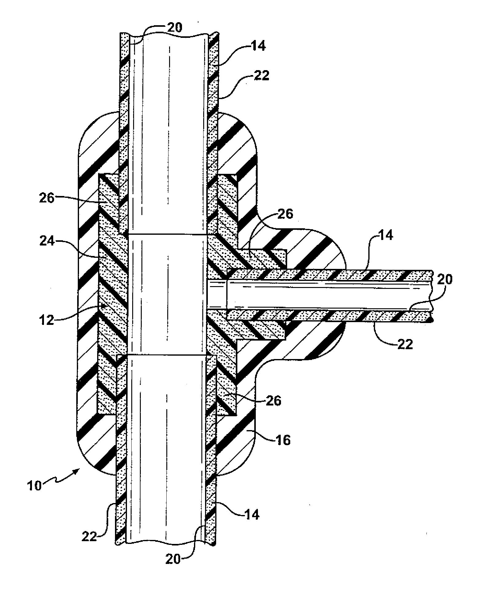
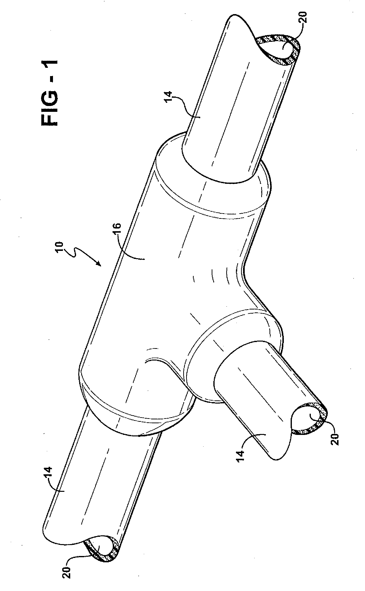
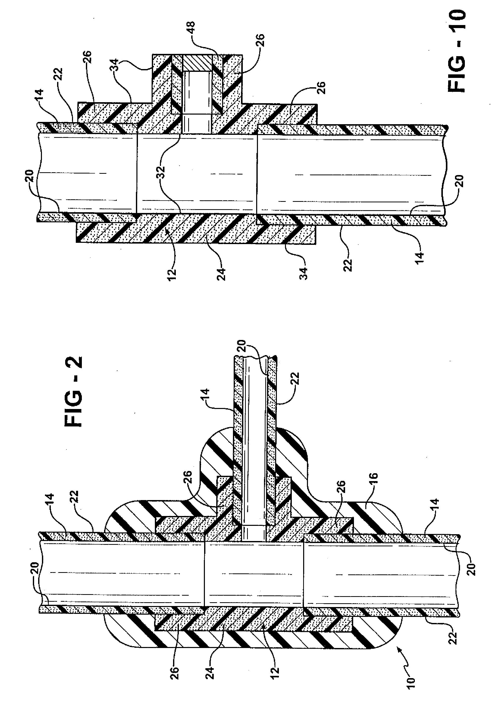
[0027]Referring to the Figures, wherein like numerals indicate like or corresponding parts throughout the several views, a fluid transfer assembly is generally shown at 10 in FIGS. 1 and 2. The fluid transfer assembly 10 includes a manifold 12 and a plurality of flexible tubes 14 inserted within the manifold 12. An outer capsule 16 is at least partially disposed over the manifold 12 and the tubes 14 after the tubes 14 are inserted within the manifold 12. The illustrative embodiment discloses the manifold 12 as substantially T-shaped having a single input and a pair of outputs. It should be appreciated that the manifold 12 may be of any suitable design or configuration, such as Y-shaped, and may include any number of inputs and any corresponding number of outputs. Similarly, the outer capsule 16 is disclosed as substantially T-shaped due to the T-shaped configuration of the manifold 12. It should also be appreciated that the outer capsule 16 may be of any suitable configuration.

[0028...


PUM

PropertyMeasurementUnit
Fractionaaaaaaaaaa
Weightaaaaaaaaaa
Thicknessaaaaaaaaaa

Abstract

A fluid transfer assembly for transporting medicinal substances. The fluid transfer assembly includes flexible tubes and a manifold each comprising silicone. The manifold has an inner protrusion and connector portions having inner walls. Free ends of the tubes are inserted into complementary configured inner walls of the connector portions until each of the free ends abut the inner protrusion, which creates a continuous uninterrupted passageway between the inner bores of the tubes through the manifold.

Description

BACKGROUND OF THE INVENTION[0001]1. Field of the Invention[0002]The subject invention relates to a fluid transfer assembly for transferring liquids, such as medicinal substances, through a number of different tubes.[0003]2. Description of Related Art[0004]Fluid transfer assemblies having T-shaped or Y-shaped connectors for interconnecting three or more flexible tubes are well known in a variety of industries, such as the medical industry and the automotive industry. A typical T-shaped connector is illustrated in U.S. Pat. No. 6,308,992. The '992 patent discloses a T-shaped connector having a series of barbs with the tubes fitting over portions of the connector and interengaging the barbs to retain the tubes onto the T-shaped connector. Although the T-shaped connector of the '992 patent is specifically designed for an automotive application, similar T-shaped connectors are used in the medical industry.[0005]Tubing used in the medical industry is frequently formed of silicone. Silicon...

Claims


Application Information

Patent Timeline
IPC IPC(8): F16L47/32F16L23/12
CPCA61M39/10Y10T403/66F16L47/32B29C65/561B29C65/70B29C66/1222B29C66/1224B29C66/1282B29C66/1284B29C66/1286B29C66/30321B29C66/52241B29C66/52292B29C66/52295B29C66/52297B29C66/71A61M2039/1083B29C65/483B29L2031/24B29L2031/246B29C45/14467B29C45/14598B29C45/14614B29C65/48B29K2083/00B29C66/73161B29K2019/00
Inventor INMAN, JR., WILLIAM D.JAHN, DONALD A.KAIN, ROBERT L.KREUCHER, THOMAS C.SAGE, JEFFREY PAULVAN ROY, BLONDINE
Owner DOW SILICONES CORP
Why Eureka
Try Eureka