Camera

a technology of camera and image, applied in the field of camera, can solve the problems of affecting the inability to restore the inability to capture the original resolution of the picture, so as to improve the apparent resolution or sharpness of the captured imag

Inactive Publication Date: 2008-11-13
OLYMPUS CORP
View PDF2 Cites 33 Cited by
  • Summary
  • Abstract
  • Description
  • Claims
  • Application Information

AI Technical Summary

Benefits of technology

[0029]The present invention has been made in view of the abovementioned problem and an object of the present invention is to provide a camera capable of improving apparent resolution or sharpness of a captured image in the case where resolution of the picture degrades due to application of geometric transformation of the captured image.

Problems solved by technology

However, in the case where the substantial number of luminance samples of a captured image is insufficient relative to the number of recorded pixels of the captured image or the number of displayed pixels thereof (number of pixels per unit area is less than that of original one), the captured image is inevitably recorded or displayed with a degraded resolution.
The reason for this is that the degradation in the resolution of the picture due to the insufficient number of luminance samples depends on the sampling theorem, so that it is impossible to restore original resolution of the picture by means of general image processing unless resolution information is added by retouching processing.
In the case where the resolution of the picture degrades due to the insufficient number of luminance samples after application of the abovementioned geometric transformation, apparent resolution or sharpness of the captured image is impaired from the viewpoint of the visual feature of human eyes (first problem).
However, even though the above method can improve the apparent resolution or sharpness of the captured image by simply amplifying the amplitude level of edges of the image, these edges of the image becomes a bold line when the captured image is magnified with the result that the bold line is unnaturally emphasized (second problem).
However, in the abovementioned CG apparatus, a problem (third problem) that a geometric transformation apparatus should achieve high-speed image processing when it is incorporated in a camera is not solved.
That is, this CG apparatus does not satisfy requirements, such as being moderate in price, having a small-scale circuit, having a smaller time lag between capturing of an optic image and display of the captured image, which are necessary for the geometric transformation apparatus to be incorporated in a camera.
In the video camera disclosed in Jpn. Pat. Appln. KOKAI Publication No. 11-239294, the first problem that the apparent resolution or sharpness of a captured image is impaired and third problem that a geometric transformation apparatus should achieve high-speed image processing when it is incorporated in a camera have been solved.
However, the second problem that edges of the image of a captured image is unnaturally emphasized as a bold line has not yet been solved.
Thus, in the image processing apparatus, the second problem that edges of the image of a captured image is unnaturally emphasized as a bold line has not yet been solved.
However, in the digital signal processing circuit disclosed in Jpn. Pat. Appln. KOKAI Publication No. 2000-101870, the third problem that a geometric transformation apparatus should achieve high-speed image processing when it is incorporated in a camera has not been solved.
As described above, the digital signal processing circuit disclosed in Jpn. Pat. Appln. KOKAI Publication No. 2000-101870 needs to incorporate an image analyzing circuit for analyzing an input video signal in order to perform the phase control of the interpolated pixels, inevitably increasing the circuit scale with the result that a high-speed image processing cannot be performed.

Method used


Image

  • Camera
  • Camera
  • Camera

Examples


first embodiment

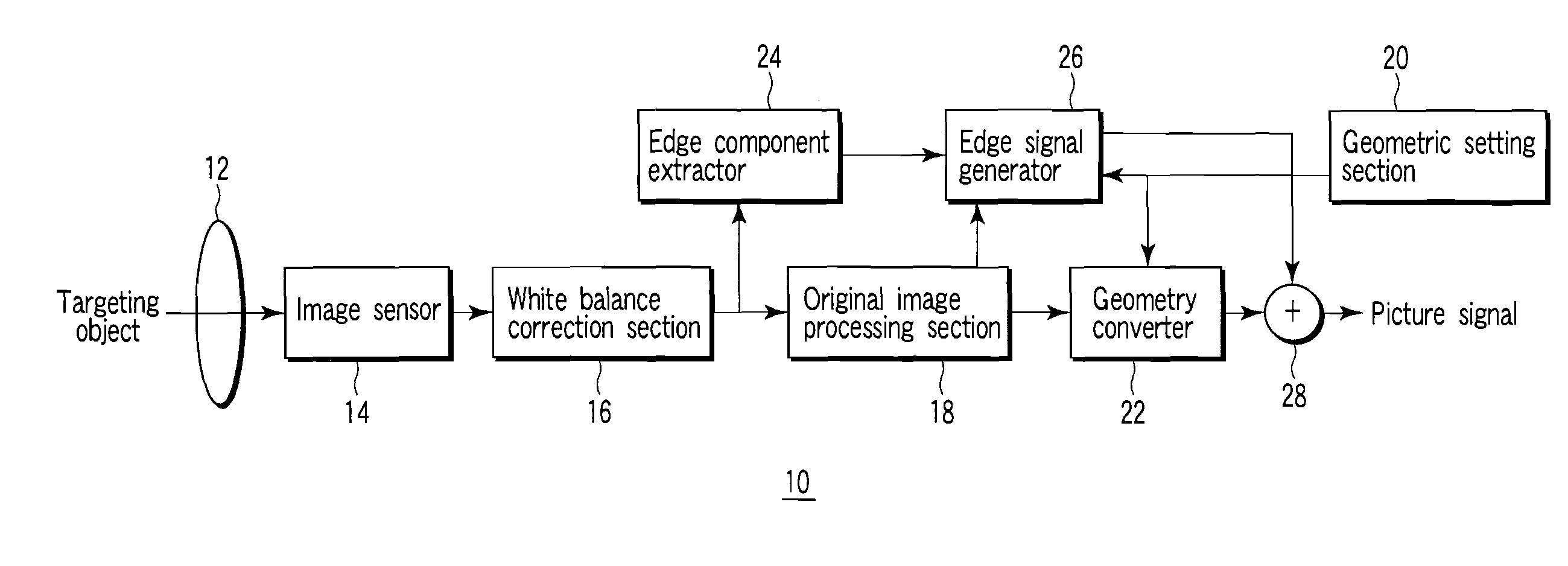
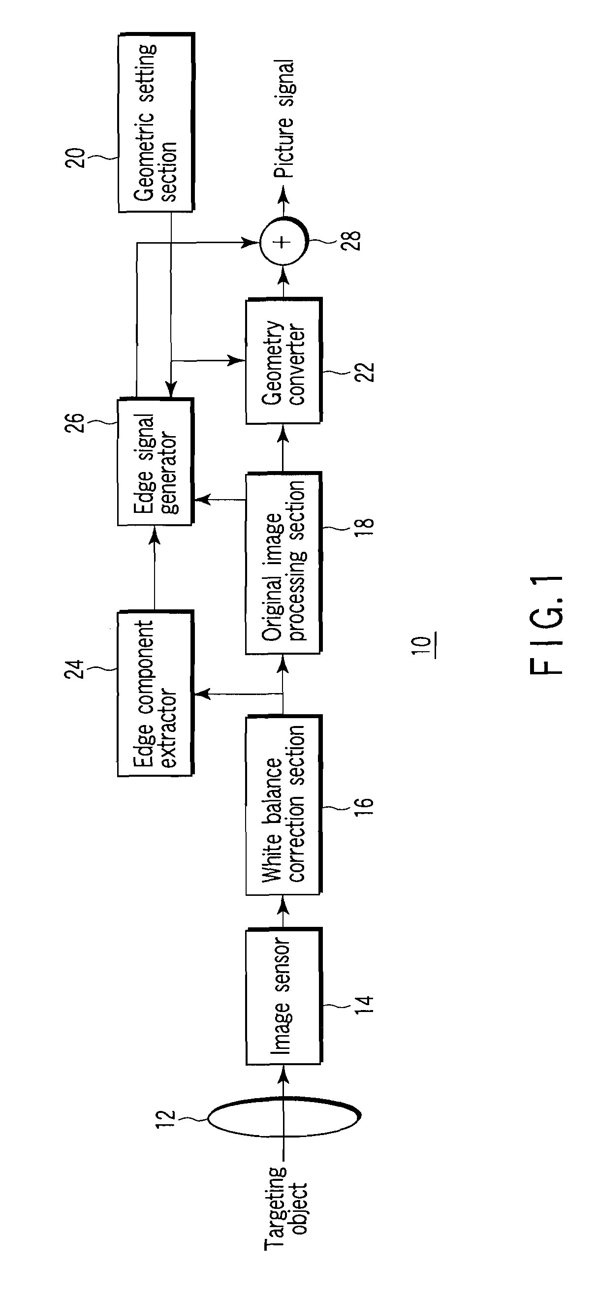
[0056]FIG. 1 is a block diagram showing a configuration of a camera according to a first embodiment of the present invention.

[0057]In FIG. 1, a camera 10 includes an optical system 12, an image sensor 14, a white balance correction section 16, an original image processing section 18, a geometric setting section 20, a geometry converter 22, an edge component extractor 24, an edge signal generator 26, and an image synthesizer 28.

[0058]The optical system 12 generates an optic image from a targeting object. The image sensor 14 photoelectric converts the optic image generated in the optical system 12 to generate a output signal from image sensor. The white balance correction section 16 corrects the white balance of the output signal from image sensor to generate a white balanced imaging signal. The original image processing section 18 generates an original picture signal from the white balanced imaging signal. These components are used in a typical camera.

[0059]The geometric setting sect...

second embodiment

[0137]A second embodiment of the present invention will be described below.

[0138]The second embodiment of the present invention is a camera having a configuration in which the edges of the image extractor shown in the first embodiment according to the thinning-out single color extraction method is made conforming to, e.g., a high-speed electronic viewfinder (EVF).

[0139]FIG. 15 is a block diagram showing a configuration of a camera according to the second embodiment of the present invention.

[0140]The basic configuration and operation of the camera according to the second embodiment are the same as those of the camera according to the first embodiment shown in FIG. 1. Thus, in FIG. 15, the same reference numerals as those in FIG. 1 are used for the same parts as those in FIG. 1, and the descriptions thereof will be omitted and different configuration and different operation from the first embodiment will be described.

[0141]In FIG. 15, a camera 30 includes an optical system 12, an imag...


PUM


Abstract

A camera includes an optical system, an image sensor, a white balance correction section, an original image processing section, a geometric setting section which sets a desired geometric transformation for the original picture signal, a geometry converter which generates a geometrically converted picture signal based on the geometric setting made by the geometric setting section, an edge component extractor, an edge signal generator, and an image synthesizer which synthesizes the geometrically converted picture signal and signal at the edges to generate a picture signal. The edge signal generator performs geometrical transformation of the edges of the image based on the geometric setting and is parameter-controlled based on a geometry parameter computed from a coefficient to emphasize edges for controlling the enhancement at the edges amount for the edges of the image and magnification to zoom an image calculated based on the geometric setting.

Description

CROSS-REFERENCE TO RELATED APPLICATIONS[0001]This application is based upon and claims the benefit of priority from prior Japanese Patent Application No. 2007-125618, filed May 10, 2007, the entire contents of which are incorporated herein by reference.BACKGROUND OF THE INVENTION[0002]1. Field of the Invention[0003]The present invention relates to a camera for generating a signal at the edges from a captured image based on a geometric setting.[0004]2. Description of the Related Art[0005]A technique relating to a video camera is disclosed in, e.g., Jpn. Pat. Appln. KOKAI Publication No. 11-239294. This publication describes a video camera provided with an electronic zoom function including: an image capture means for focusing a targeting object image and outputting a video signal based on the focused image; a high-frequency component extraction means for extracting a high-frequency component of the video signal; a gain setting means for setting a gain in the high-frequency component ...

Claims


Application Information

Patent Timeline
Patent Type & Authority Applications(United States)
IPC IPC(8): H04N9/73
CPCH04N3/1562H04N5/23296H04N9/045G06T5/003G06T7/0085G06T2207/10024G06T2207/20192G06T3/403G06T7/13H04N23/63H04N23/69H04N23/843H04N25/134
Inventor OTSU, HIRONAO
Owner OLYMPUS CORP
Why Eureka
Try Eureka