Multi-plane cell switch fabric system

a switch fabric and multi-plane technology, applied in the field of multi-plane cell switch fabric system, can solve problems such as lowering the switching capacity, and achieve the effects of low switching capacity, high switching capacity, and cost reduction

Active Publication Date: 2008-11-13
ALAXALA NETWORKS
View PDF34 Cites 38 Cited by
  • Summary
  • Abstract
  • Description
  • Claims
  • Application Information

AI Technical Summary

Benefits of technology

[0020]Applying the present invention to a multi-plane cell switch in which each switch functions asynchronously with others will thus realize distributing and restoring processings that do not lower the switching capacity. Furthermore, this will make it possible to realize a method for restori...

Problems solved by technology

In case of each multi-plane cell switch in which each switching unit functions asynchronously with others, the switch has been confronted with a problem of how to prevent lowering of the switching capacity that might otherwise be caused by distributing an...

Method used


Image

  • Multi-plane cell switch fabric system
  • Multi-plane cell switch fabric system
  • Multi-plane cell switch fabric system

Examples


first embodiment

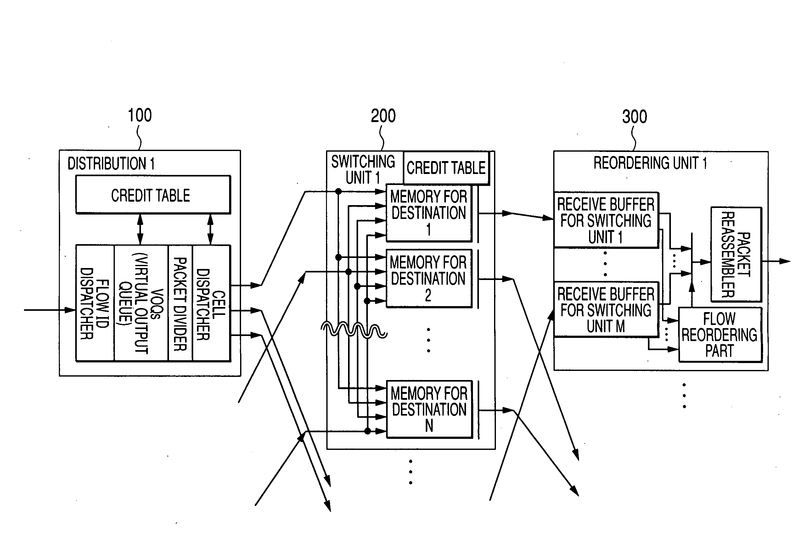
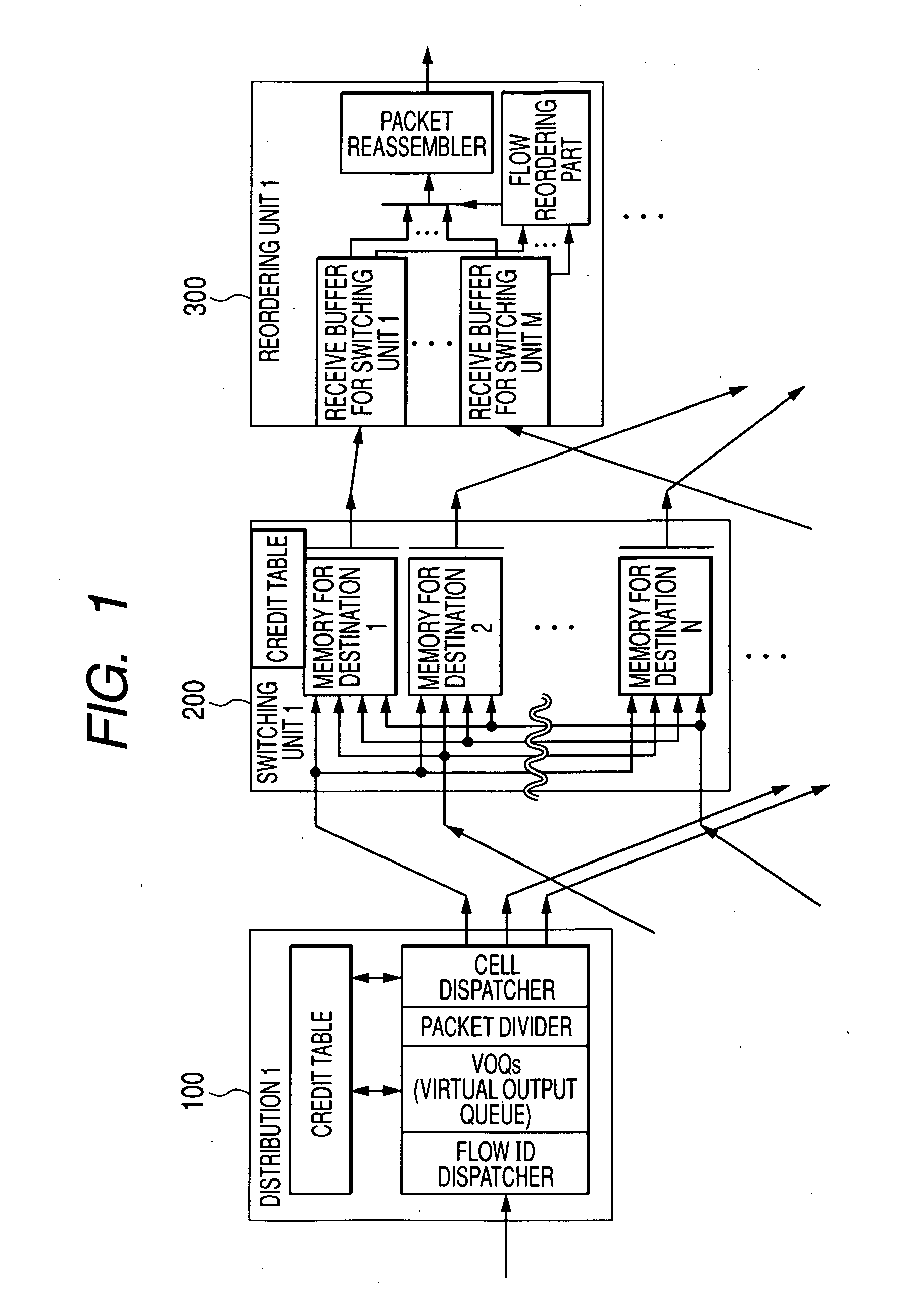
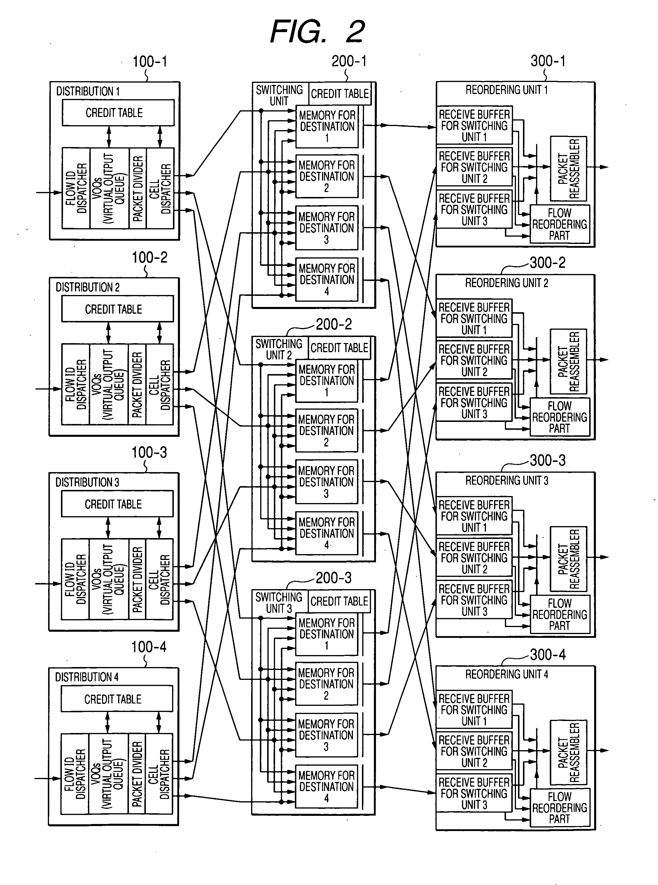
[0040]FIG. 1 shows a configuration of a multi-plane cell switch fabric system in an embodiment of the present invention. The multi-plane cell switch fabric system includes “N” distribution units 100, each of which functions as an input, “M” switching units 200 used for switching data respectively, and “N” reordering units 300, each of which functions as an output. Note that, however, FIG. 1 shows only part of the multi-plane cell switch fabric system so as to simplify the configuration; the number of input / output units, as well as the number of switching units can be decided freely. For example, FIG. 2 shows another configuration of the entire multi-plane cell switch fabric system that includes 4 input / output units and 3 switching units. In other words, the multi-plane cell switch fabric system is composed of 4 distribution units 100-[1 to 4], 3 switching units 200-[1 to 3], and 4 reordering units 300-[1 to 4].

[0041]At first, how each unit of the switch fabric system will function w...

second embodiment

[0111]Next, there will be described a second embodiment of a multi-plane cell switch fabric system including a reordering unit capable of restoring each flow in a shorter time than the reordering unit in the first embodiment. The configurations of the distribution unit 100 and the switching unit 200 in this second embodiment are the same as those described with reference to FIG. 1, etc. in the first embodiment. As for the configuration of the reordering unit, there is only a difference between this second embodiment and the first embodiment; a flow reordering part is provided in the reordering unit in this second embodiment. Therefore, there will be described the configuration and operation of only the flow reordering part 330′ in detail in this second embodiment.

[0112]The flow reordering part 330′ in this second embodiment, as shown in FIG. 15, includes a sequence number management memory 332, a sequence number comparator 333, a receive-buffer-read queue 335, a retry queue 336, a c...


PUM


Abstract

Disclosed herewith is a multi-plane cell switch fabric system in which each switching unit functions asynchronously with others. The system executes distribution/restoration operations without lowering the switching capacity to reorder cells that arrive in random order from a plurality of switches just as they were in original flows and packets respectively with a small hardware capacity. In the system, the distribution unit divides each variable length packet addressed to the same destination into fixed length cells and sends those divided cells by a unit of integer multiple of the number of switches. On the other hand, the reordering unit, while holding cells that arrive in random order from each switching unit (switching units 1 to M) in a receive buffer, separates only the header information from each cell and holds the header information in a retry queue. The reordering unit, upon finding the header information of a head cell of a flow in an ordering check at the time of receiving or in a retry check in the retry queue, extracts the corresponding cell bodies from the receive buffer to restore the original order of those cells in the subject packet.

Description

CLAIM OF PRIORITY[0001]The present application claims priority from Japanese application JP 2007-122014 field on May 7, 2007, the content of which is hereby incorporated by reference into this application.FIELD OF THE INVENTION[0002]The present invention relates to a switching technique for connecting a plurality of functional blocks provided in such an apparatus as a router, a server, a storage, etc. dynamically to each another, more particularly to a technique for utilizing a plurality of independently functioning switches to sort data into their original order if they do not arrive at their destination in order of their original sequential numbers.BACKGROUND OF THE INVENTION[0003]In a network transfer apparatus such as a router, in a server, and in a storage unit for connecting a plurality of disk arrays, a switch fabric for switching data among the functional blocks in itself is used. The switching capacity of such a switch fabric is represented with a product of the number of p...

Claims


Application Information

Patent Timeline
IPC IPC(8): H04L12/56H04L47/43
CPCH04L49/1523H04L49/3027H04L49/3072H04L49/508H04L49/552
Inventor OKUNO, MICHITAKA
Owner ALAXALA NETWORKS
Why Eureka
Try Eureka