Fuel Cell System

a fuel cell and system technology, applied in the field of fuel cell systems, can solve the problems of gas shortage and insufficient performance of electric power generation of fuel cells, and achieve the effect of narrowing the effective reaction cross section of mea

Active Publication Date: 2008-11-13
HONDA MOTOR CO LTD
View PDF3 Cites 30 Cited by
  • Summary
  • Abstract
  • Description
  • Claims
  • Application Information

AI Technical Summary

Benefits of technology

[0012]In the fuel cell system described above, when the cold start of the system is determined by the cold start determination means, the fuel gas exchange means increases the total discharge amount of the gas to be discharged by opening the discharge valve for exchanging the atmosphere inside the fuel gas flow path for the fuel gas, and increases the fuel gas concentration in the fuel gas flow path. As a result, the fuel gas concentration reaches to a concentration with which the MEA can normally conduct the electrode reaction even if the effective reaction cross section of the MEA is narrowed by, for example, freezing.
[0030]According to the present invention, a fuel cell system can be provided, in which when the system is started with a cold start, the fuel cell system is hardly becomes short of fuel gas in a MEA after electric power generation is started even if an effective reaction cross section of the MEA is narrowed.

Problems solved by technology

Therefore, when the fuel cell is started after the shutdown, the anode may become short of hydrogen, thereby resulting in insufficient performance of electric power generation of the fuel cell.
Especially, the shortage of the gas tends to take place when a current output (output current) from the fuel cell is increased for increasing self-heating to promote warming up of the fuel cell since the fuel cell might freeze.

Method used


Image

  • Fuel Cell System
  • Fuel Cell System
  • Fuel Cell System

Examples


Embodiment Construction

[0036]Hereinafter, one embodiment of the present invention will be explained by referring to figures as needed.

>

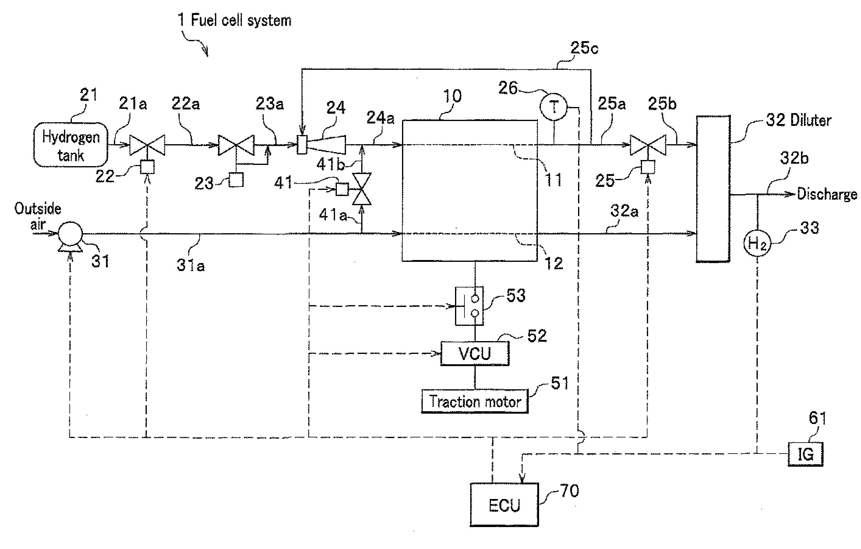
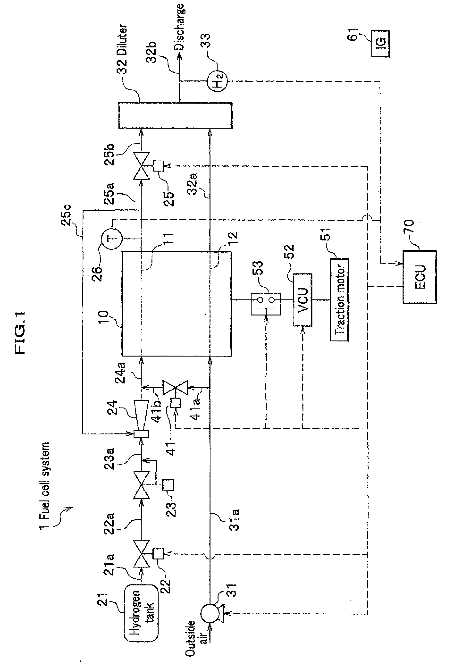
[0037]A fuel cell system 1 according to the embodiment shown in FIG. 1 is installed in a fuel cell vehicle (mobile object), which is not shown. The fuel cell system 1 includes a fuel cell stack 10, an anode system (fuel gas supplying means) supplying and discharging hydrogen (fuel gas) to and from an anode of the fuel cell stack 10, a cathode system supplying and discharging air (oxidant gas) including oxygen to and from a cathode of the fuel cell stack 10, a scavenging system introducing a scavenging gas (non-humidified air) to the anode system from the cathode system when the fuel cell stack 10 is scavenged, an electric power consuming system consuming, for example, an electric power generated by the fuel cell stack 10, IG 61 (ignition), and ECU 70 (electronic control unit) electronically controlling constituents described above.

[0038]Here, a scavenging of the fuel cell ...


PUM

PropertyMeasurementUnit
temperatureaaaaaaaaaa
temperature T1aaaaaaaaaa
concentrationaaaaaaaaaa

Abstract

A fuel cell system which includes: a fuel cell having a fuel gas flow path and an oxidant gas flow path and generating electricity by being supplied a fuel gas to the fuel gas flow path and an oxidant gas to the oxidant gas flow path; fuel gas supplying means; a discharge valve; fuel gas exchange means for exchanging an atmosphere inside the fuel gas flow path for the fuel gas at a starting of the system; and cold start determination means for determining whether to conduct or not to conduct the cold start of the system, wherein when the cold start determination means determines to conduct the cold start, the cold start determination means increases a total discharge amount of a gas to be discharged for exchanging the atmosphere inside the fuel gas flow path for the fuel gas, and thereby increases a fuel gas concentration in the fuel gas flow path.

Description

CROSS REFERENCE TO RELATED APPLICATIONS[0001]This application claims the foreign priority benefit under Title 35, United States Code, §119(a)-(d) of Japanese Patent Application No. 2007-122008, filed on May 7, 2007, the contents of which are hereby incorporated by reference.BACKGROUND OF THE INVENTION[0002]1. Field of the Invention[0003]The present invention relates to a fuel cell system.[0004]2. Description of Related Art[0005]In recent years, a development of a fuel cell such as a polymer electrolyte fuel cell (hereinafter, referred to as PEFC), which generates electricity by being supplied hydrogen to the anode and air (oxidant gas) containing oxygen to the cathode, is more popular than before. The fuel cell described above includes an anode flow path (fuel gas flow path) through which the hydrogen is supplied to and discharged from the anode flows, and a cathode flow path (oxidant gas flow path) through which the air is supplied to and discharged from the cathode flows.[0006]How...

Claims


Application Information

Patent Timeline
Patent Type & Authority Applications(United States)
IPC IPC(8): H01M8/04
CPCH01M8/04231Y02E60/50
Inventor OGAWA, JUMPEIWAKE, CHIHIRO
Owner HONDA MOTOR CO LTD
Why Eureka
Try Eureka