Assessment of Electrode Coupling For Tissue Ablation

a tissue ablation and electrode technology, applied in the field of electrode catheters, can solve the problems of difficult to determine the contact between electrodes and tissue, the difficulty of ensuring adequate tissue contact between electrodes, and the inability to achieve tissue ablation. , to achieve the effect of increasing the potential and reducing the potential of puncturing the tissue wall or membran

Active Publication Date: 2008-11-13
ST JUDE MEDICAL ATRIAL FIBRILLATION DIV
View PDF24 Cites 118 Cited by
  • Summary
  • Abstract
  • Description
  • Claims
  • Application Information

AI Technical Summary

Benefits of technology

[0046]Each of the first through the seventh aspects may be used to identify the existence of an elevated or excessive coupling condition. The ability to identify the existence of such an elevated or excessive coupling condition may be desirable for a number of reasons. For instance, it may be desirable to avoid an elevated or excessive coupling condition (e.g., to reduce the potential of puncturing a tissue wall or membrane). It also may be desirable to reach an elevated or excessive coupling condition (e.g., to increase the potential of passing the first electrode through a tissue wall or membrane).

Problems solved by technology

Several difficulties may be encountered, however, when attempting to form lesions at specific locations using some existing ablation electrodes.
One such difficulty encountered with existing ablation electrodes is how to ensure adequate tissue contact and electrical coupling.
Electrode-tissue contact is not readily determined using conventional techniques such as fluoroscopy.
Such experience only comes with time, and may be quickly lost if the physician does not use the electrode catheter on a regular basis.
In addition, when forming lesions in a heart, the beating of the heart further complicates matters, making it difficult to determine and maintain sufficient contact pressure between the electrode and the tissue for a sufficient length of time to form a desired lesion.
If the contact between the electrode and the tissue cannot be properly maintained, a quality lesion is unlikely to be formed.
Similarly, information on electrical coupling between the electrode and the target tissue is not readily available a priori to determine how much ablative energy may be absorbed in the tissue during ablation.
Such experience may lead to deficiencies, inefficiencies and complications, such as inadequate lesion formation, premature high impedance shut-off, tissue charring, and thrombus formation.

Method used


Image

  • Assessment of Electrode Coupling For Tissue Ablation
  • Assessment of Electrode Coupling For Tissue Ablation
  • Assessment of Electrode Coupling For Tissue Ablation

Examples


Embodiment Construction

[0071]Exemplary embodiments of a tissue ablation system and methods of use to assess electrode-tissue contact and electrical coupling are depicted in the figures. As described further below, the tissue ablation system of the present invention provides a number of advantages, including, for example, the ability to apply a reasonable amount of ablative energy to a target tissue while mitigating electrode-tissue contact and coupling problems. The invention also facilitates enhanced tissue contact and electrical coupling in difficult environments (e.g., during lesion formation on a surface inside a beating heart).

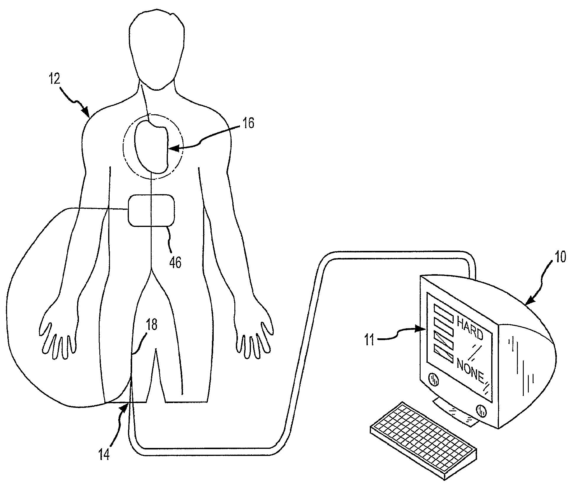
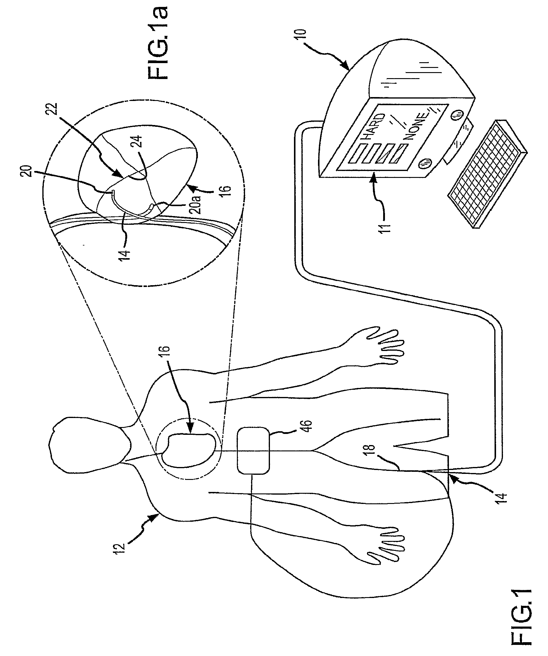
[0072]FIG. 1 is a diagrammatic illustration of an exemplary electrode catheter system 10 which may be implemented to assess electrode-tissue contact during a tissue ablation procedure for a patient 12. Catheter system 10 may include an electrode catheter 14, which may be inserted into the patient 12, e.g., for forming ablative lesions inside the patient's heart 16. During an ex...


PUM


Abstract

An electrode catheter and a method for assessing electrode-tissue contact and coupling are disclosed. An exemplary electrode catheter comprises an electrode adapted to apply electrical energy. A measurement circuit is adapted to measure impedance between the electrode and ground as the electrode approaches a target tissue. A processor determines a contact and coupling condition for the target tissue based at least in part on reactance of the impedance measured by the measurement circuit. In another exemplary embodiment, the electrode catheter determines the contact and coupling condition based at least in part on a phase angle of the impedance.

Description

CROSS-REFERENCE TO RELATED APPLICATIONS[0001]This application claims the benefit of U.S. provisional application No. 60 / 748,234, filed on 6 Dec., 2005, which is incorporated herein by reference. This application is also related to international application docket no. 0B-047801WO, docket no. 0B-047810US, docket no. 0B-047811US, docket no. 0B-047812US, docket no. 0B-047813US, docket no. 0B-047814US and docket no. 0B-047815US, being filed concurrently herewith (“international applications”). The international applications are incorporated herein by reference.BACKGROUND OF THE INVENTION[0002]a. Field of the Invention[0003]The instant invention is directed toward an electrode catheter and a method for using the electrode catheter for tissue ablation. In particular, the electrode catheter of the present invention may comprise a circuit to assess electrode-tissue contact and electrical coupling for applying ablative energy (e.g., RF energy) to target tissue.[0004]b. Background Art[0005]It ...

Claims


Application Information

Patent Timeline
Patent Type & Authority Applications(United States)
IPC IPC(8): A61B18/14A61B5/296
CPCA61B18/1492A61B2018/00666A61B2018/00357A61B2018/00702A61B2018/0075A61B2018/00755A61B2018/00869A61B2018/00875A61B2019/464A61B2019/465A61B18/1206A61B2018/00303A61B2018/00577A61B2018/00642A61B19/5244A61B34/20A61B2090/064A61B2090/065A61B5/053
Inventor PAUL, SAURAVCAO, HONGBELHE, KEDAR RAVINDRATHAO, CHOU
Owner ST JUDE MEDICAL ATRIAL FIBRILLATION DIV
Why Eureka
Try Eureka