Washing machine with steam generator
a technology of steam generator and washing machine, which is applied in the field of washing machines, can solve the problems of increasing the size of the washing machine, increasing the material cost, and requiring more spa
- Summary
- Abstract
- Description
- Claims
- Application Information
AI Technical Summary
Benefits of technology
Problems solved by technology
Method used
Image

Examples
first embodiment
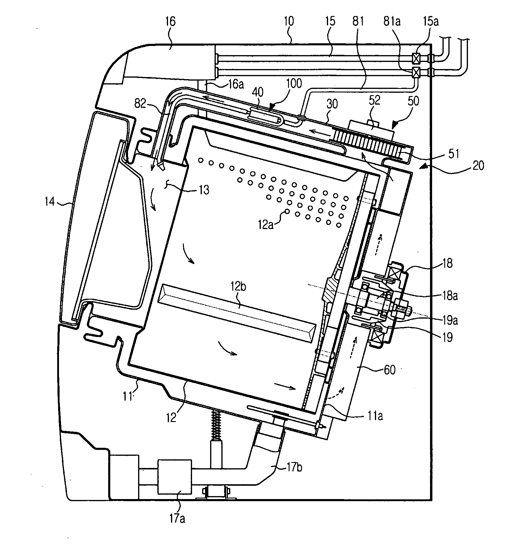
[0055]FIG. 3 is a sectional view illustrating the structure of a washing machine FIG. 4 is a perspective view illustrating a heating duct, a heater, and a steam generating part of FIG. 3, and FIG. 5 is an exploded perspective view illustrating the coupling between the heater and the steam generating part of FIG. 4.
[0056]As shown in FIG. 3, the washing machine according to the present embodiment includes a machine body 10 forming an external appearance of the washing machine, a stationary tub 11 mounted in the machine body 10 to receive water, and a rotary tub 12 rotatably mounted in the stationary tub 11. In the front of the machine body 10 is formed a laundry inlet port 13, through which laundry is put in the rotary tub 12. To the front of the machine body is mounted a door 14 to open and close the laundry inlet port 13.
[0057]At an inside upper part of the machine body 10 are mounted a first water supply pipe 15 to supply wash water and a detergent supply unit 16 to supply deterge...
second embodiment
[0079]FIG. 8 is a perspective view illustrating a heating duct, a heater, and a steam generating part of a washing machine FIG. 9 is an exploded perspective view illustrating the coupling between the heater and the steam generating part of FIG. 8, and FIG. 10 is a sectional view taken along line I-I of FIG. 8.
[0080]Hereinafter, only the characteristics of this embodiment will be described, and components of this embodiment, which are common to those of the previous embodiment shown in FIGS. 3 to 5, will be denoted by the same reference numerals.
[0081]According to this embodiment, as shown in FIGS. 8 to 10, a steam generating plate 120, a bottom 120a of which contacts the heater 40, is used as the object 101. The steam generating plate 120 is constructed to receive water, which will be changed into steam. Water, supplied to the steam generating plate 120, is changed into steam by the heat emitted from the heater 40. The steam is supplied to the rotary tub 12 (see FIG. 3) through the...
third embodiment
[0090]FIG. 11 is a perspective view illustrating a heating duct, a heater, and a steam generating part of a washing machine and FIG. 12 is a sectional view taken along line I-I of FIG. 11. FIGS. 3 to 10 illustrate examples using the pipe-type heater, whereas this embodiment illustrates an example using a positive temperature coefficient (PTC) heater. Hereinafter, only the characteristics of this embodiment will be described.
[0091]As shown in FIGS. 11 and 12, a PTC heater 45 is used as the heater mounted in the heating duct 30. The PTC heater 45 includes a plurality of heat dissipation fins 46 arranged in parallel to one another and a PTC heating rod 47 penetrating the heat dissipation fins 46. Each heat dissipation fin 46 has a through-hole 46a formed in the center thereof. The PTC heating rod 47 is inserted through the through-holes 46a of the heat dissipation fins 46.
[0092]On the heat dissipation fins 46 of the PTC heater 45 are mounted a steam generating plate 130 as the object ...
PUM
 Abstract
Description
Claims
Application Information
 - Generate Ideas
- Intellectual Property
- Life Sciences
- Materials
- Tech Scout
- Unparalleled Data Quality
- Higher Quality Content
- 60% Fewer Hallucinations
Browse by: Latest US Patents, China's latest patents, Technical Efficacy Thesaurus, Application Domain, Technology Topic, Popular Technical Reports.
© 2025 PatSnap. All rights reserved.Legal|Privacy policy|Modern Slavery Act Transparency Statement|Sitemap|About US| Contact US: help@patsnap.com