Two-step roller finger cam follower

a roller finger cam and follower technology, applied in the direction of valve details, valve springs, valve arrangements, etc., can solve the problems of increased force requirements of lost motion and valve springs, inconvenient operation, and inability to adjust the angle of the roller finger cam, etc., to achieve the effect of reducing the range of lost motion of the central slider, reducing the force requirements of the lost motion and the valve spring, and reducing the overall volum

Inactive Publication Date: 2008-11-20
DELPHI TECH INC
View PDF4 Cites 19 Cited by
  • Summary
  • Abstract
  • Description
  • Claims
  • Application Information

AI Technical Summary

Benefits of technology

[0018]A spool-shaped roller comprising a shaft and opposed roller elements attached to the shaft is disposed in the shaft orifices, the rollers being adapted to follow the surface motion of the low-lift cam lobes. Preferably, the shaft is journalled in roller or needle bearings which extend between and through both the first and second shaft orifices, being thus exposed to normal copious oil flow through central regions of the RFF.
[0019]A slider arm for engaging a high-lift cam lobe is disposed in the slider arm aperture and is pivotally mounted on a common axis with the roller shaft and includes a slider tip for engaging an activation / deactivation latch pin. The latch pin is slidably and at least partially disposed in the latch pin channel and has a nose section for extending from the channel to selectively engage the slider tip, to switch modes of the RFF assembly.

Problems solved by technology

A drawback of all such prior art two-step RFF assemblies is that the mass of the central slider, and therefore the moment of rotational inertia, is undesirably high, which increases the force requirements of the lost motion and valve springs.
Another drawback is that the overall volume, and therefore the engine space consumed, is undesirably large.
Still another drawback is that the range of lost motion of the central slider is constrained by practical limits of mechanical strength imposed by the arcuate slot in the central slider for accommodating the axle of the low-lift rollers.
Still another drawback is that the number of components is undesirably large, resulting in relatively high component manufacturing and assembly costs.
Still another drawback is that provision for a rotational stop to limit leakdown of an associated HLA requires special manufacturing and assembly components and procedures.
A serious drawback of this two-step RFF assembly is that it requires complicated component shapes and features to implement the locking function.
Further, packaging and assembly of the slider bias springs is difficult and problematic.

Method used


Image

  • Two-step roller finger cam follower
  • Two-step roller finger cam follower
  • Two-step roller finger cam follower

Examples


Embodiment Construction

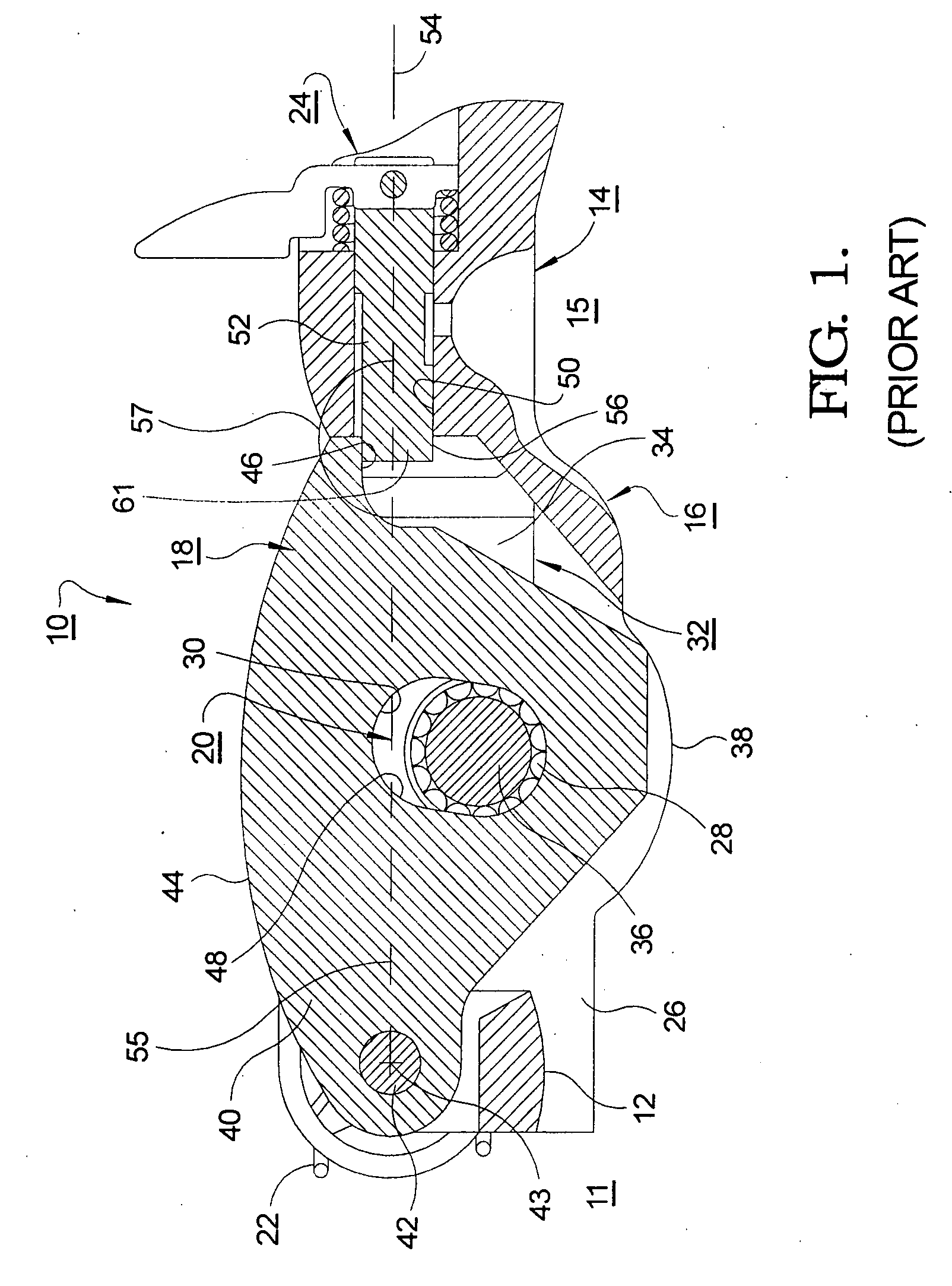
[0031]The benefits and advantages of a two-step RFF assembly in accordance with the present invention may be better appreciated by first considering a prior art two-step RFF assembly.

[0032]Referring to FIG. 1, prior art two-step RFF assembly 10 is substantially as shown in U.S. Pat. No. 6,755,167 B2. Pallet end 12 of prior art RFF 10 is provided for engaging a valve stem 11 and socket end 14 is provided for engaging the hemispherical head of a hydraulic lash adjuster 15. RFF 10 includes body assembly 16, slider arm assembly 18, spool roller assembly 20, lost motion spring 22, and latch assembly 24.

[0033]Body assembly 16 includes elongate body 26 and roller bearing 28 disposed in bearing orifices 30. Elongate body 26 includes a slider arm aperture 32 bounded by body side walls 34 defining bearing orifice 30 therethrough. The diameter of bearing orifice 30 is sized to press-fittedly receive roller bearings 28. A cross-shaft 36 is rotatably disposed in bearing 28 and is supportive of r...


PUM


Abstract

A two-step roller finger follower assembly for shifting between high-lift and low-lift valve modes in a valve train of an internal combustion engine includes a body having side members defining coaxially disposed shaft orifices, a pallet end, a socket end, a slider arm aperture, and a latch pin channel. The socket end is mountable to a hydraulic lash adjuster, and the pallet end is matable with a valve stem. A slider arm for engaging a high-lift cam lobe is disposed in the aperture, is pivotably mounted to a rotatable cross-shaft extending through the shaft orifices, and includes a slider tip for selectively engaging a latch pin to latch or unlatch the slider arm from the body. Dual rollers on the cross-shaft follow dual low-lift cam lobes. Preferably, the slider arm has a compound radial surface to provide compound lost motion of the slider arm, thereby minimizing rotational inertia.

Description

TECHNICAL FIELD[0001]The present invention relates to roller finger followers used for variable valve actuation in overhead cam type internal combustion engines; and more particularly, to a roller finger follower assembly having a body supportive of an axle shaft for dual outboard rollers for following a corresponding pair of cam lobes, and a central slider arm for following a central cam lobe between the pair of lobes; and most particularly, to such an assembly wherein the slider is pivotably mounted on the axle shaft.BACKGROUND OF THE INVENTION[0002]Roller Finger Followers (RFFs) are widely used in overhead cam internal combustion engines to sequentially open and close the cylinder intake and exhaust valves. In a typical application, the RFF assembly serves to transfer and translate rotary motion of a camshaft eccentric lobe into a pivotal motion of the RFF assembly to thereby open and close an associated valve.[0003]It is known that, for a portion of the duty cycle of a typical m...

Claims


Application Information

Patent Timeline
Patent Type & Authority Applications(United States)
IPC IPC(8): F01L1/047
CPCF01L1/18F01L1/182F01L1/185F01L13/0005F01L13/0036F01L2105/00F01L2001/186F01L2305/00
Inventor HENDRIKSMA, NICK J.
Owner DELPHI TECH INC
Why Eureka
Try Eureka