Method and appratus for insertion of an Anti-siphon grid into a hose

a technology of anti-siphon grid and hose, which is applied in the direction of mechanical equipment, manufacturing tools, transportation and packaging, etc., can solve the problems of inconvenience to the vehicle operator, unauthorized access to the fuel filler tube, and general ineffectiveness, so as to eliminate the undesirable shortcomings and eliminate the previous undesirable complications

Inactive Publication Date: 2008-11-20
FLUID ROUTING SOLUTIONS
View PDF10 Cites 3 Cited by
  • Summary
  • Abstract
  • Description
  • Claims
  • Application Information

AI Technical Summary

Benefits of technology

[0010]The recent push for alternative fuels has created increasing efforts to make automobile compatible with fuels such as E85 (85% ethanol / 15% gasoline). In making automobiles compatible with such fuels, a number of safety requirements associated with the fuel fill assembly and the fuel tank of such automobiles are necessary. One of these requirements is to provide protection against the siphoning of the E85 fuel from the tank. In accordance with the present invention, a method and apparatus are provided for inserting an anti-siphon device in a rubber fuel hose, wherein the anti-siphon device has an outer diameter larger that the inner diameter of rubber hose into which the anti-siphon device is inserted. The method and apparatus for installing the anti-siphon device in the rubber fuel hose provides for the anti-siphon device to be inserted through one or more various bends in the rubber hose, and for securing the anti-siphon device in the rubber hose such that the anti-siphon device is positioned in a square relationship with that portion of the hose in which the anti-siphon device is installed. That is, the longitudinal axis of the anti-siphon device, installed in accordance with the present invention, corresponds to the longitudinal axis of that portion of the rubber hose in which the anti-siphon device is installed. The anti-siphon device installed accordingly not only prevents theft of fuel from the automotive fuel tank, but it also eliminates the undesirable shortcomings of similar anti-siphon devices installed according to previously known methods.
[0011]According to a first embodiment of the invention, a method for installing the anti-siphon device into a rubber hose is described, wherein the anti-siphon device is installed in the rubber hose at a position that not only prevents siphoning of fuel from the fuel tank, but also eliminates the previous undesirable complications of fuel flow turbulence associated with known anti-siphon devices.
[0012]According to another embodiment of the invention, an apparatus is described for carrying out the method for installing the anti-siphon device in a rubber hose at a position that not only prevents siphoning of fuel from the fuel tank, but also eliminates the previous undesirable complications associated with known anti-siphon devices.

Problems solved by technology

In recent years, the ever increasing price of liquid hydrocarbon fuel has been accompanied by a corresponding increase in liquid hydrocarbon fuel related thefts.
Such devices are easily opened allowing unauthorized access to the fuel filler tube and are therefore, generally ineffective.
Furthermore, most of such locking devices require the use of a key which is an inconvenience to the vehicle operator.
Also, such lock mechanisms are subject to malfunction during cold and inclement weather.
While snapping the anti-siphoning device onto the end of the fill pipe is a convenient way of installing the anti-siphoning device into the fuel fill apparatus, the close proximity of the anti-siphoning device to the nozzle generally causes the grids of the anti-siphoning device to provide undesirable turbulence in the flow of fuel often resulting in premature shut-off of the fuel being pumped into the fuel tank.
Such prior art anti-siphoning devices are not only operationally complicated, but the manufacture of such devices is labor intensive and economically unattractive because of the requirement for costly compressing and welding tools.
Since, for economical purposes, the outside diameter of the anti-siphon device is typically larger that the inside diameter of the rubber fuel fill hose, there exists a major problem of inserting the anti-siphon device into the rubber hose.
Furthermore, the rubber fuel fill hose typically is a curved hose having one or more various degrees of bend which hinders the placing of the anti-siphon device in a square relationship with respect to the portion the fuel fill hose in which the anti-siphon device is installed.

Method used


Image

  • Method and appratus for insertion of an Anti-siphon grid into a hose
  • Method and appratus for insertion of an Anti-siphon grid into a hose
  • Method and appratus for insertion of an Anti-siphon grid into a hose

Examples


Embodiment Construction

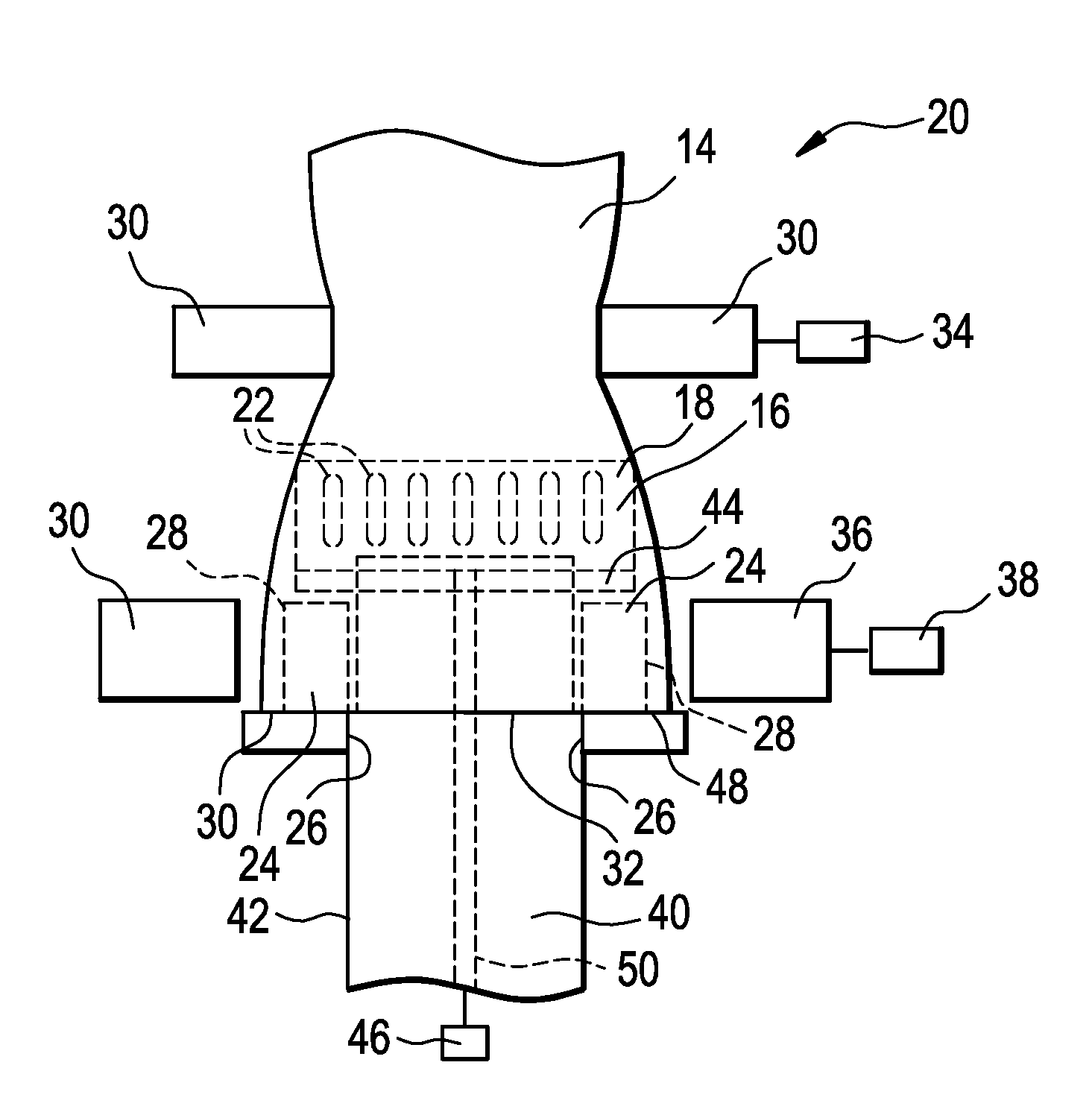
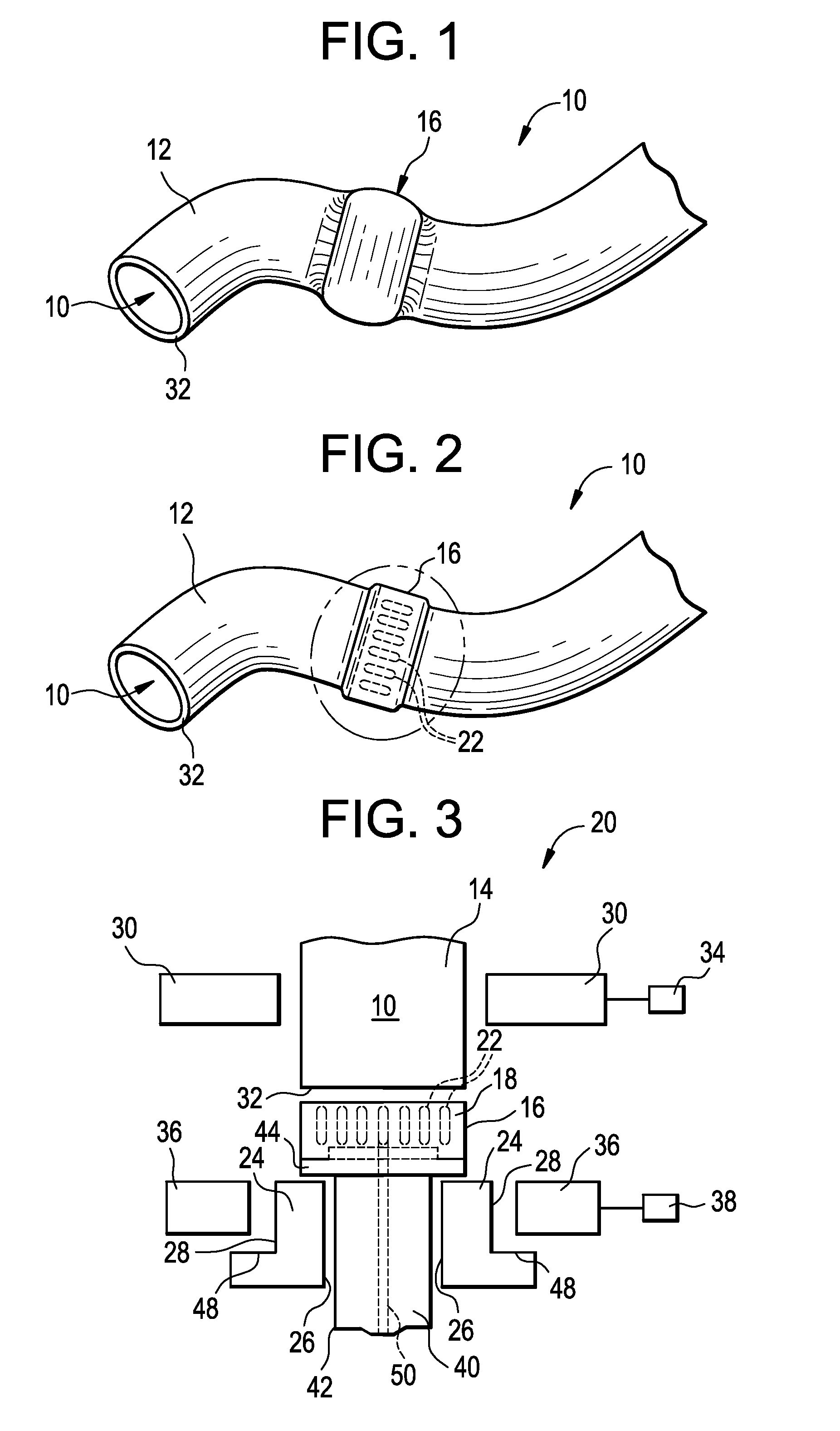
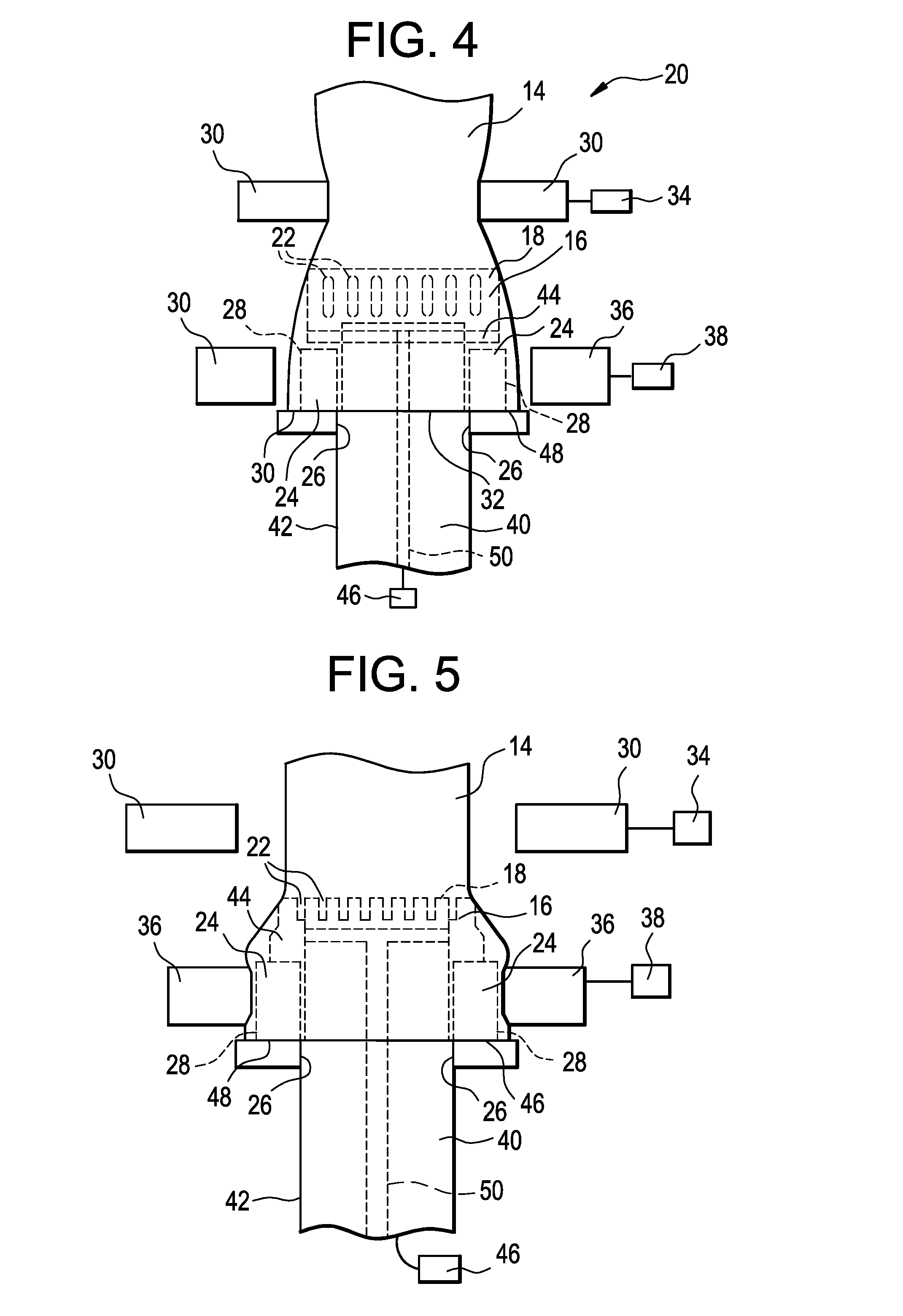
[0019]Typically, the anti-siphoning device is a relatively simple device having a cylindrical side portion and base providing a plurality of apertures such as grid members having alternating parallel and perpendicular members, or parallel ribs strategically positioned in the device and configured in such manner to allow fuel to flow unrestricted through the device while preventing any sort of siphoning tube from being inserted through the device and into the fuel tank.

[0020]The fuel filler hose in an automotive vehicle is a curved structure configured to have several bends which may be slight or acute in one or more directions. The curved configuration of the hose is necessary because of limited space available in the construction of the vehicle. While such hoses are relatively flexible, they are formed to resist appreciable deformation. Therefore, attempts to permanently insert an anti-siphon device into such hose so that the device is aligned in the hose to prevent adverse effects...


PUM

PropertyMeasurementUnit
distanceaaaaaaaaaa
rigidaaaaaaaaaa
flexibleaaaaaaaaaa

Abstract

An apparatus for installing an anti-siphon device into an automotive fuel filler comprises; a cylindrical mandrel having an inner surface and an outer surface, the outer surface of the mandrel adapted to receive a proximal end of the hose; a first grasping means configured to grasp the hose at a predetermined distance from a proximal end of the hose, and to insert the proximal end of the hose onto the outer surface of the mandrel; a first actuating means for inducing the first grasping means to grasp the hose at the predetermined distance from the proximal end of the hose, and to insert the proximal end of the hose onto the outer surface of the mandrel; a second grasping means configured to grasp and hold the proximal end of the hose on the mandrel during installation of the anti-siphon device in the hose; a second activating means for inducing the second grasping means to grasp the proximal end of the hose on the mandrel, and hold the hose thereon during installation of the anti-siphon device into the hose; an anti-siphon device insertion means having an outer surface, the anti-siphon device insertion means disposed in the mandrel, wherein the outer surface of the anti-siphon device insertion means is adjacent the inner surface of the mandrel; an anti-siphon device fixture disposed on one end of the anti-siphon device insertion means, wherein the anti-siphon device fixture is adapted to receive the anti-siphon device thereon; and a third activating means for inserting the anti-siphon device inserting means having the anti-siphon device disposed thereon, into the hose and withdrawing the anti-siphon device inserting means to the mandrel upon installing the anti-siphon device in the hose. A method is also described.

Description

BACKGROUND OF THE INVENTION[0001]The present invention relates to automotive fuel systems and particularly to the installation of various devices such as an anti-siphon devices, into a fuel fill hose. More particularly, the invention relates to a method and apparatus for the installation and alignment of the device, e.g., anti-siphon device, in the hose for preventing the siphoning of fuel from an automotive fuel tank.[0002]In recent years, the ever increasing price of liquid hydrocarbon fuel has been accompanied by a corresponding increase in liquid hydrocarbon fuel related thefts. Typically, the theft of such fuel is accomplished by siphoning the fuel from any relatively large fuel tank associated with liquid-fuel-powered machinery, e.g., automobiles, trucks, generators, etc.[0003]Siphoning of fuel from a fuel tank generally involves placing a tubular structure through the fuel filler inlet or opening and into the fuel tank. A vacuum, such as suction pressure is applied to the opp...

Claims


Application Information

Patent Timeline
Patent Type & Authority Applications(United States)
IPC IPC(8): F16L55/10
CPCY10T29/53552B60K15/0403Y10T137/0486
Inventor HATCHETT, JOELHOLT, BEN F.PERRY, JIMMY
Owner FLUID ROUTING SOLUTIONS
Why Eureka
Try Eureka