
Cylindrical vibration isolating device

Active Publication Date: 2008-11-20
HONDA MOTOR CO LTD +1
View PDF11 Cites 17 Cited by
  • Summary
  • Abstract
  • Description
  • Claims
  • Application Information

AI Technical Summary

Benefits of technology

[0015]According to the invention as defined in the first aspect, since the boundary portion is changed in height in the axial direction of the outer cylinder such that the contact area between the inner peripheral surface of the mounting hole and the large diameter portion is gradually increased, when the outer cylinder is press-fitted into the mounting hole provided in the mounted member, the press fitting load at the time of press fitting is gradually increased in accordance with the press fitting stroke so that there is no rapid rise in the press fitting load thereby to prevent the bad influence by the rapid rise in the press fitting load.
[0016]According to the invention as defined in the second aspect, since the boundary portion is formed substantially in an inverted U-shape, the rapid rise preventing structure of the press fitting load can be easily formed.
[0018]According to the invention as defined in the fourth aspect, the axially extending cavity is formed in the vibration isolating rubber in the vicinity of the top of the boundary portion, and the solid connecting leg for connecting the inner cylinder and the outer cylinder is formed in the vibration isolating rubber in the vicinity of the bottom, so that it is possible to decrease the influence upon spring of the vibration isolating rubber because of reduction of the diameter of the outer cylinder at the time of press fitting.
[0020]According to the invention as defined in the sixth aspect, since the forward end portion at the time of mounting is formed as the engaging head portion of vibration isolating rubber which projects from the outer cylinder, the vibration isolating rubber of the engaging head portion can be kept free without restraint of the outer cylinder until mounting. Therefore, the vibration isolating rubber can be released from a molding deformation before mounting, thereby making it possible to improve the durability.

Problems solved by technology

This rapid rise of the press fitting load causes such a bad influence that the rubber seal portion “c” is damaged or that a crack is developed in a welded portion of the sub-frame.

Method used


Image

  • Cylindrical vibration isolating device
  • Cylindrical vibration isolating device
  • Cylindrical vibration isolating device

Examples


Embodiment Construction

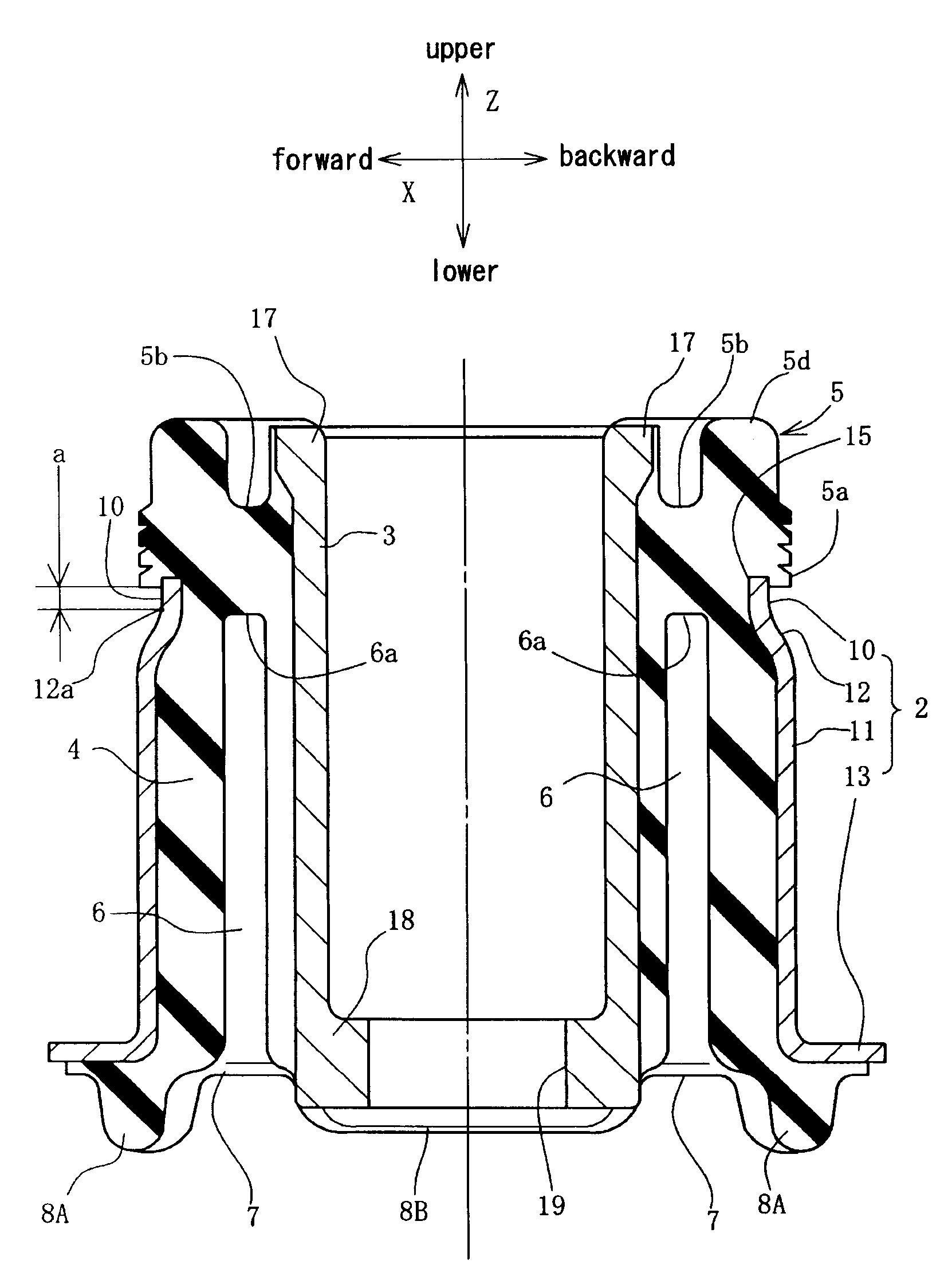
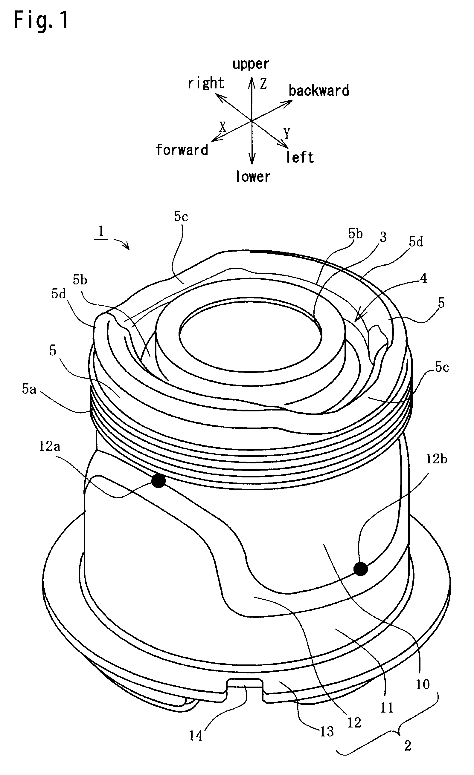
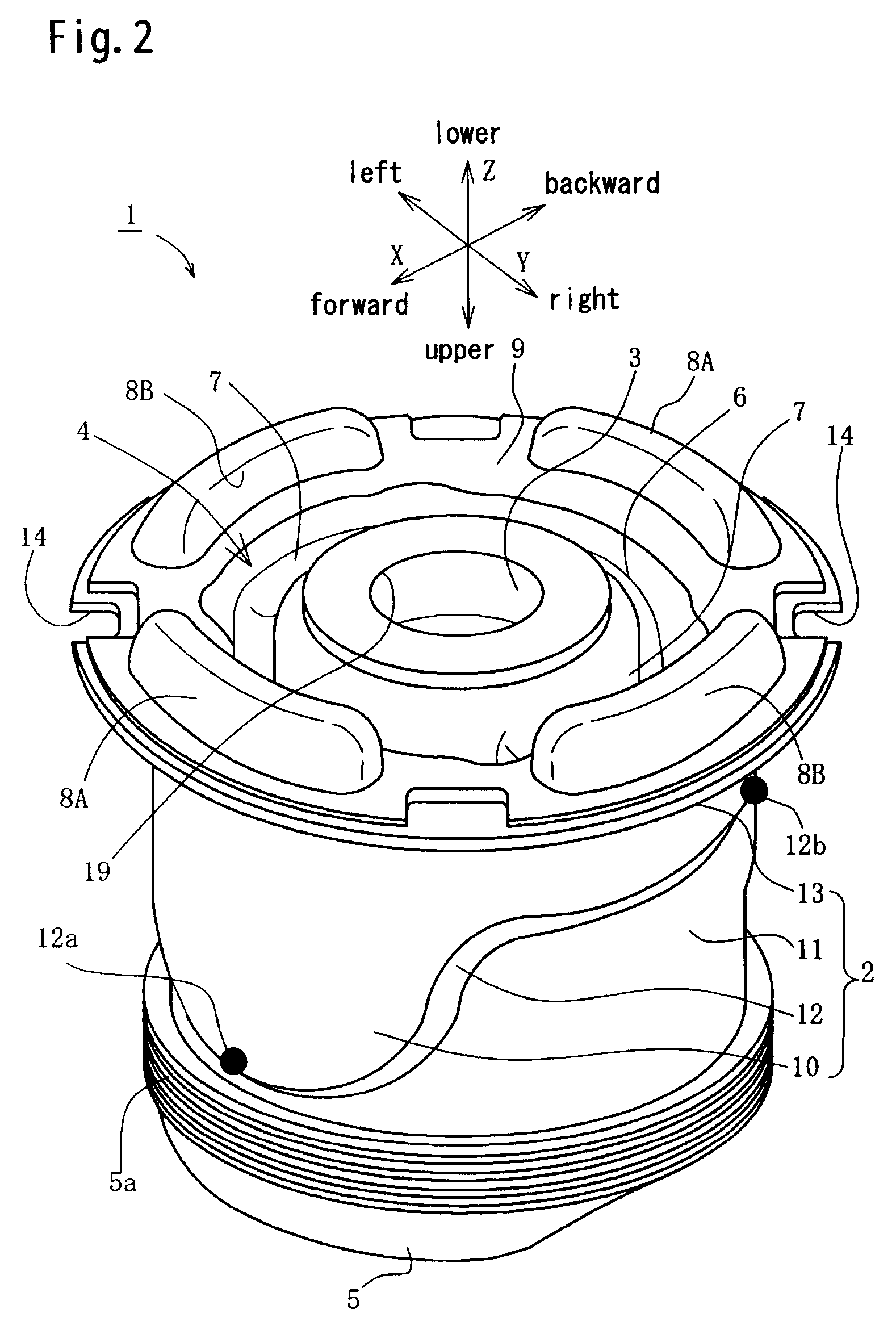
[0033]Hereinafter, an embodied example applied to a sub-frame mount will be explained with reference to the accompanying drawings, wherein FIG. 1 is a perspective view of the sub-frame mount according to the first embodied example of the present invention, FIG. 2 is a perspective view thereof which is turned upside down, FIG. 3 is a bottom view thereof, FIG. 4 is a front view thereof, FIG. 5 is a side view thereof, FIG. 6 is a cross sectional view taken on the line 6-6 of FIG. 3, FIG. 7 is a cross sectional view taken on the line 7-7 of FIG. 3, FIG. 8 is a cross sectional view taken on the line 8-8 of FIG. 5, FIG. 9 is a cross sectional view taken on the line 9-9 of FIG. 5, and FIG. 10 is a partial cross sectional view taken along the line 6-O-7 of FIG. 3. In this embodied example, each direction of the sub-frame mount such as an upper and lower direction, a forward and backward direction and a right and left direction is fixed on the basis of a mounted state on the vehicle body, Mo...


PUM


Abstract

The object of the present invention is to prevent damages of a vibration isolating rubber and cracks in a welded portion of a sub-frame when press-fitting a sub-frame mount.The sub-frame mount 1 comprises an outer cylinder 2, an inner cylinder 2 and the vibration isolating rubber 4 connecting these outer and inner cylinders. A small diameter portion 10 and a large diameter portion 11 are provided on a lateral wall of a barrel portion of the outer cylinder 2. Between the small diameter portion 10 and the large diameter portion 11 is formed a step-like boundary portion 12. The height in the axial direction of the boundary portion 12 changes in the circumferential direction and has a substantially mountain-like shape with a top 12a projecting in the press fitting direction. A contact area of the large diameter portion 11 contacting a mounting hole 21 of the sub-frame 20 is increased in accordance with an amount of the press fitting. Therefore, when the sub-frame mount 1 is press-fitted into the mounting hole 21 of the sub-frame 20, the press fitting load is gradually increased thereby preventing the rapid rise of the press fitting load.

Description

BACKGROUND OF THE INVENTION[0001]1. Field of the Invention[0002]The present invention relates to a cylindrical vibration isolating device suitable for a sub-frame mount of motor vehicles[0003]2. Description of the Related Art[0004]As an example of cylindrical vibration isolating devices in which an inner cylinder and an outer cylinder are connected by a vibration isolating rubber, there is known a sub-frame mount. This sub-frame mount is the cylindrical vibration isolating device having the inner and outer cylinders connected by the vibration isolating rubber, and has a large diameter portion formed of a vibration isolating rubber or the like on a partial surface of the outer cylinder. The large diameter portion is adapted to be press-fitted into a mounting hole of the sub-frame (as an example, see a patent reference 1).[0005]Patent reference 1: Japanese patent laid-open publication No. 2004-211791.[0006]FIG. 11 is a graph showing a change in a press fitting load when the sub-frame ...

Claims


Application Information

Patent Timeline
IPC IPC(8): F16F15/00
CPCF16F1/387
Inventor MIYAHARA, TETSUYAOGAWA, TSUTOMUNAKAMARU, YUICHIMUTO, YUJI
Owner HONDA MOTOR CO LTD
Features
  • Generate Ideas
  • Intellectual Property
  • Life Sciences
  • Materials
  • Tech Scout
  • Unparalleled Data Quality
  • Higher Quality Content
  • 60% Fewer Hallucinations
Learn More