Resonant actuator

a technology of resonance actuator and actuator, which is applied in the direction of generator/motor, piezoelectric/electrostrictive/magnetostrictive device, piezoelectric/electrostrictive/magnetostriction machine, etc., can solve the problems of resonance frequency fr reduction, and achieve large saturated vibration velocity, reduce resonance frequency fr and mechanical quality factor qm, and reduce displacement

Inactive Publication Date: 2008-11-20
MURATA MFG CO LTD
View PDF11 Cites 19 Cited by
  • Summary
  • Abstract
  • Description
  • Claims
  • Application Information

AI Technical Summary

Benefits of technology

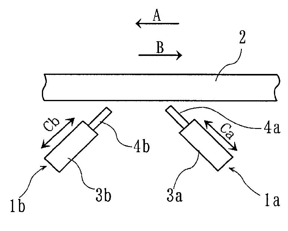
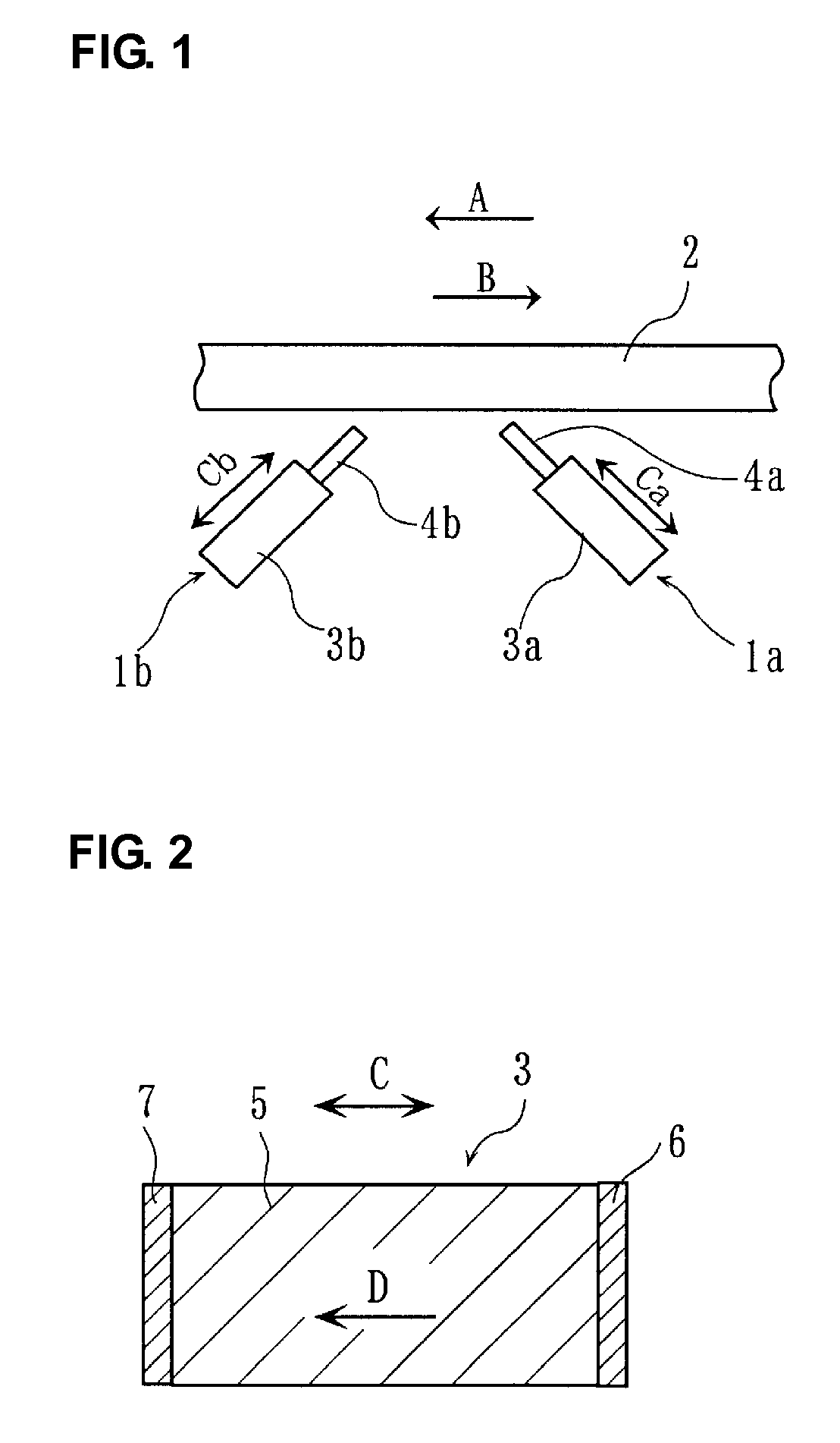
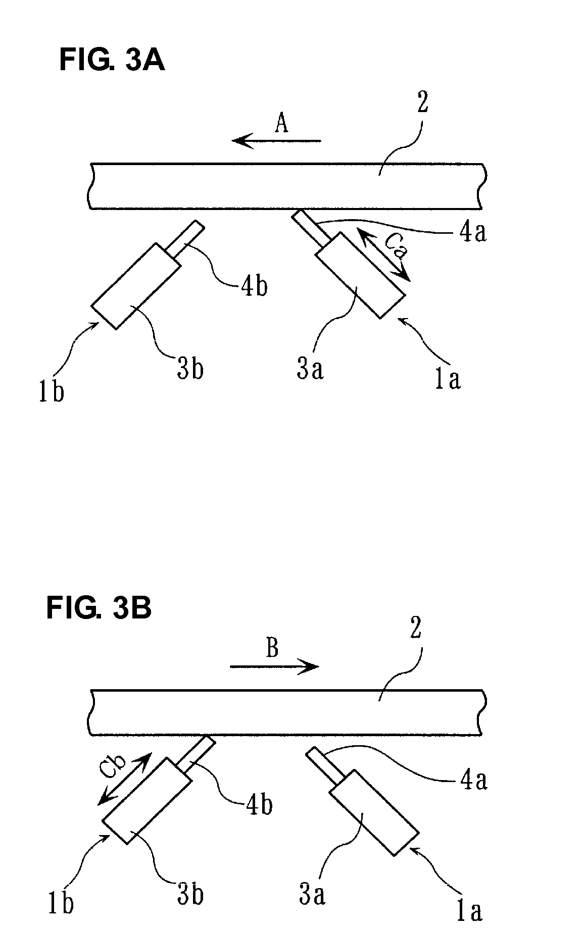
[0012]To overcome the problems described above, preferred embodiments of the present invention provide a resonant actuator having a large saturated vibration velocity, minimizing reductions in resonance frequency fr and mechanical quality factor Qm without the destabilization of the vibration velocity even at a high vibration velocity, and having a large amount of displacement even at a high electric field.

Problems solved by technology

However, as described in “Description of the Related Art”, in PZT piezoelectric ceramic materials, the increase in vibration velocity v results in the reduction in mechanical quality factor Qm and in resonance frequency fr.

Method used


Image

  • Resonant actuator
  • Resonant actuator
  • Resonant actuator

Examples


example 1

[0072]Displacement elements of samples 1 and 2 each having a displacement direction substantially the same as a polarization direction were prepared with a non-oriented Bi2srNb2O9 (hereinafter, referred to as an “SBN”) material, which is a bismuth layered compound, and a c-axis-oriented SBN material were used.

[0073]AS COMPARATIVE EXAMPLE, sample 3 having a displacement direction substantially the same as a polarization direction and sample 4 having a displacement direction substantially perpendicular to a polarization direction were prepared with a PZT material.

[0074]Methods for producing Samples will be described in detail below.

Sample 1

[0075]SrCO3, Bi2O3, Nb2O5, Nd2O3, and MnCO3 were prepared as ceramic materials and measured such That the final composition satisfies the formula {100(Sr0.9Nd0.1Bi2Nb2O9)+MnO}. The measured materials were charged into a ball mill with partially stabilized zirconia (PSZ) balls and water and wet-mixed for about 16 hours in the ball mill to produce a m...

example 2

[0126]Various SBN samples having different degrees of c-axis orientation F were produced, and characteristics thereof were evaluated.

[0127]A calcined powder and plate-shaped ceramic particles were prepared by the same method and procedure as in sample 2 described in “EXAMPLE 1”.

[0128]The plate-shaped ceramic particles and the calcined powder were mixed in different ratios by weight in such a manner that the degrees of c-axis orientation F of sintered ceramic bodies were about 54%, about 75%, and about 95%. SBN specimens of sample 22 (degree of orientation F: 54%), sample 23 (degree of orientation F: about 75%), and sample 24 (degree of orientation F: about 95%) were prepared by the same methods and procedures as in Sample 2.

[0129]The degree of orientation F of each of samples 22 to 24 was calculated by the Lotgering method in the same manner as sample 2 described in “EXAMPLE 1”.

[0130]Non-oriented SBN specimens as sample 21 were prepared as in sample 1.

[0131]The vibration velocity v,...


PUM

PropertyMeasurementUnit
vibration velocityaaaaaaaaaa
thicknessaaaaaaaaaa
pressureaaaaaaaaaa

Abstract

A resonant actuator includes a driving unit having a displacement element that vibrates at a resonance frequency or in a frequency range in the vicinity of a resonance frequency and having a driven member that is driven by the displacement element, in which the displacement element has a piezoelectric ceramic body made of a bismuth layered compound. The displacement direction of the displacement element is preferably substantially the same as the direction of polarization of the piezoelectric ceramic body. The bismuth layered compound is preferably oriented such that the direction of the c crystallographic axis is substantially perpendicular to the direction of polarization of the piezoelectric ceramic body. More preferably, the degree of c-axis orientation is determined to be at least about 75% by the Lotgering method. Thereby, it is possible to provide a resonant actuator having a large saturated vibration velocity, minimizing reductions in the resonance frequency fr and the mechanical quality factor Qm without the destabilization of the vibration velocity even at a high vibration velocity, and having a large amount of displacement even at a high electric field.

Description

BACKGROUND OF THE INVENTION[0001]1. Field of the Invention[0002]The present invention relates to resonant actuators and, more specifically, to a resonant actuator including a piezoelectric ceramic material.[0003]2. Description of the Related Art[0004]The amount of displacement of a piezoelectric actuator depends upon a piezoelectric constant d. Thus, research and development of piezoelectric ceramic materials based on Pb(Zr, Ti)O3 (lead zirconate titanate: hereinafter, referred to as “PZT”) with a large piezoelectric constant have been actively conducted.[0005]For example, Sadayuki Takahashi, “Atsuden Zairyou No Shintenkai (Novel Development of Piezoelectric Material)”, TIC Corp., Nyuu Seramikkusu (New Ceramics), VOL. 11, No. 8 (1988), p. 29-34, describes large amplitude properties of a piezoelectric ceramic material because power devices such as piezoelectric actuators utilize large amplitude elastic vibrations of piezoelectric ceramic materials.[0006]The above-identified publicati...

Claims


Application Information

Patent Timeline
Patent Type & Authority Applications(United States)
IPC IPC(8): H02N2/04C04B35/00H01L41/09H01L41/187H01L41/257H01L41/39H02N2/00
CPCH01L41/0906H01L41/187H10N30/202H10N30/853
Inventor KAWADA, SHINICHIROHORIKAWA, KATSUHIROKIMURA, MASAHIKOOGAWA, HIROZUMI
Owner MURATA MFG CO LTD
Why Eureka
Try Eureka