Apparatus and mehtods for diagnosing motor-resolver system faults

a technology of resolver and diagnostic apparatus, which is applied in the direction of motor/generator/converter stopper, dynamo-electric converter control, instruments, etc., can solve the problem of difficulty in determining which of the resolver or the resolver decoder is malfunctioning

Inactive Publication Date: 2008-11-20
DAIMLER AG +3
View PDF27 Cites 24 Cited by
  • Summary
  • Abstract
  • Description
  • Claims
  • Application Information

AI Technical Summary

Problems solved by technology

There are times, however, when one of the resolvers is malfunctioning and the motor controller transmits a warning to the user indicating that the motor coupled to the malfunctioning resolver is not working properly when in fact, it is the resolver decoder that is not working properly.
Thus, it is often difficult to determine which of the resolver or the resolver decoder is malfunctioning when the motor controller transmits an error message.

Method used


Image

  • Apparatus and mehtods for diagnosing motor-resolver system faults
  • Apparatus and mehtods for diagnosing motor-resolver system faults
  • Apparatus and mehtods for diagnosing motor-resolver system faults

Examples


Embodiment Construction

[0016]The following detailed description of the invention is merely exemplary in nature and is not intended to limit the invention or the application and uses of the invention. Furthermore, there is no intention to be bound by any theory presented in the preceding background of the invention or the following detailed description of the invention.

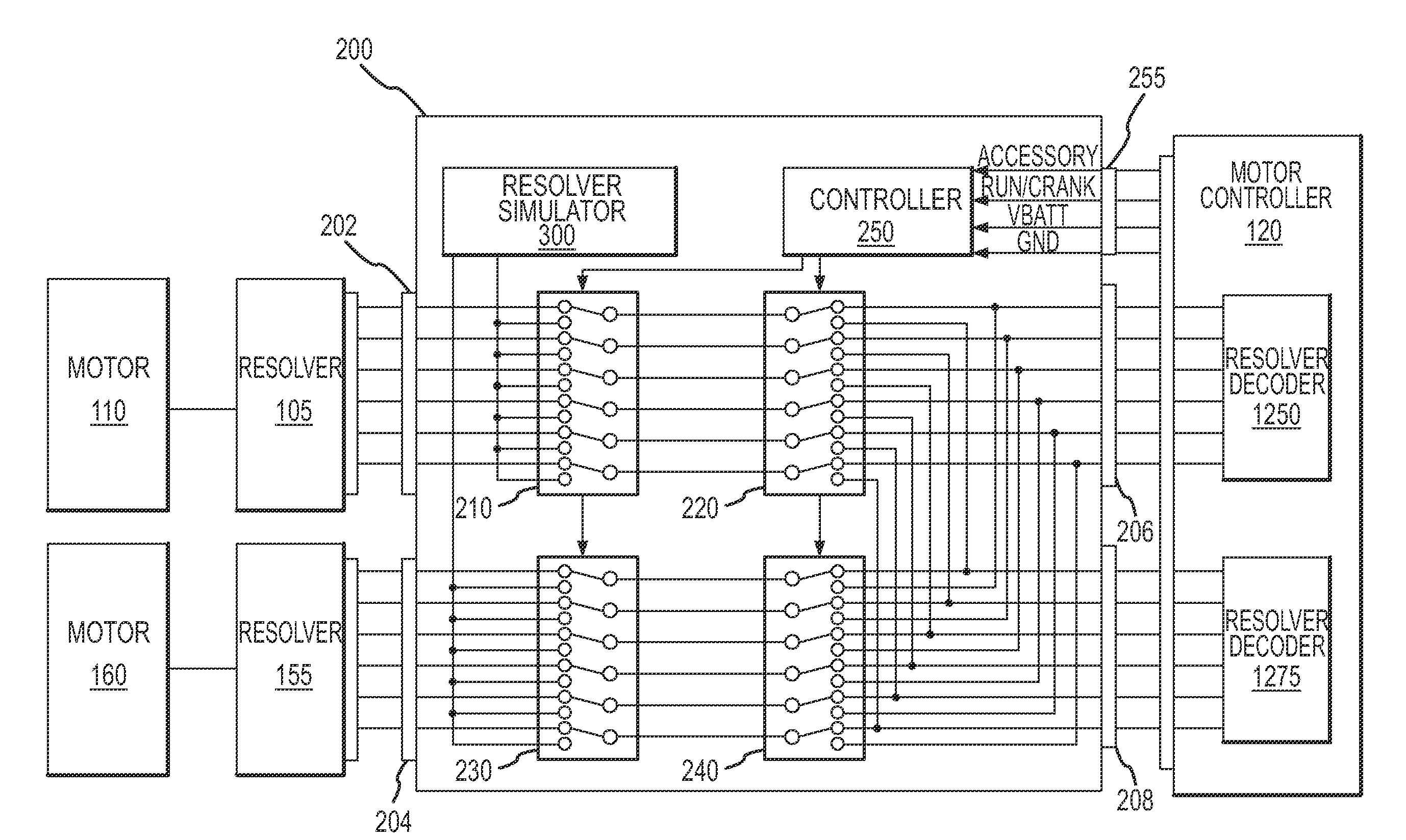
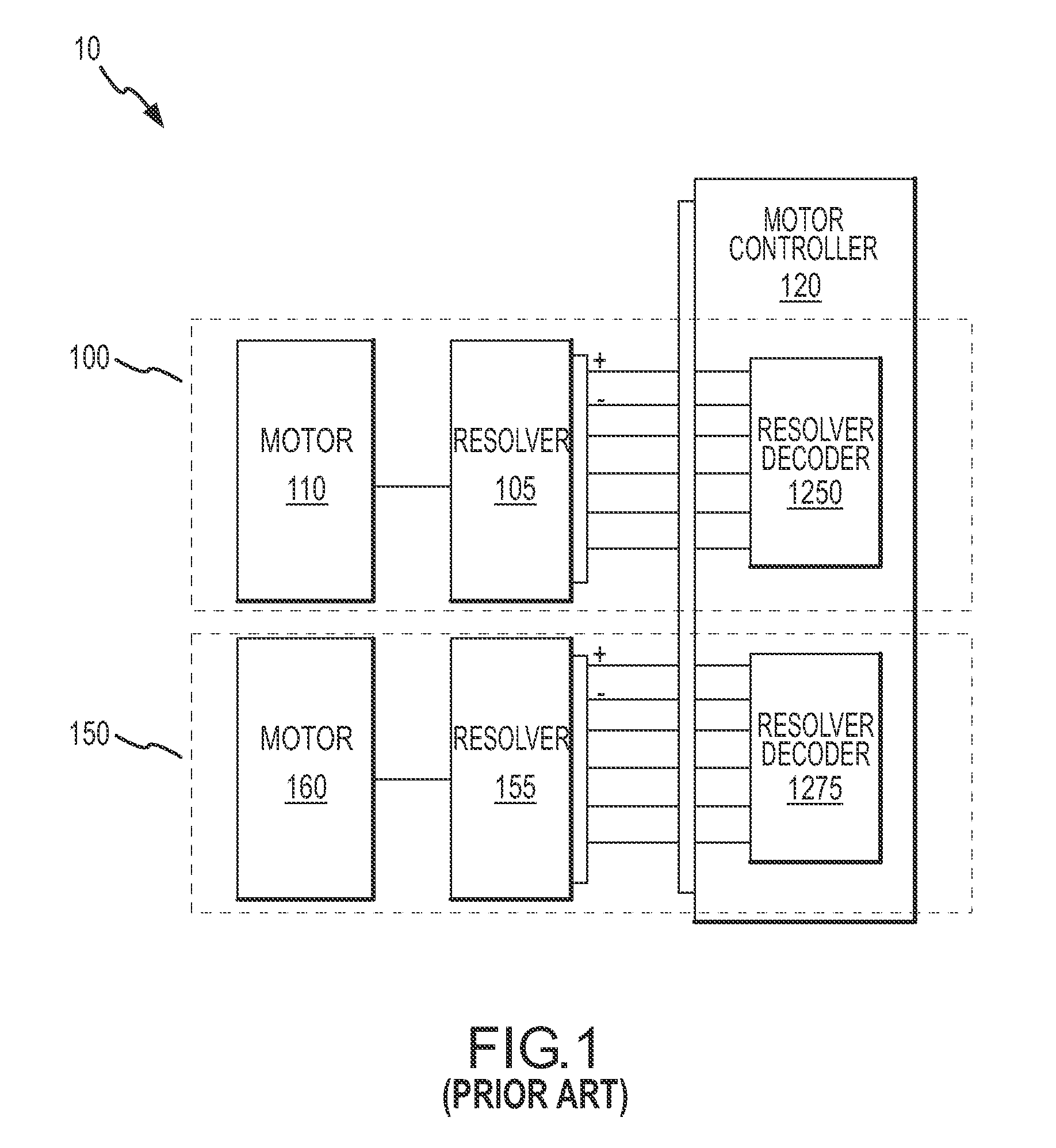
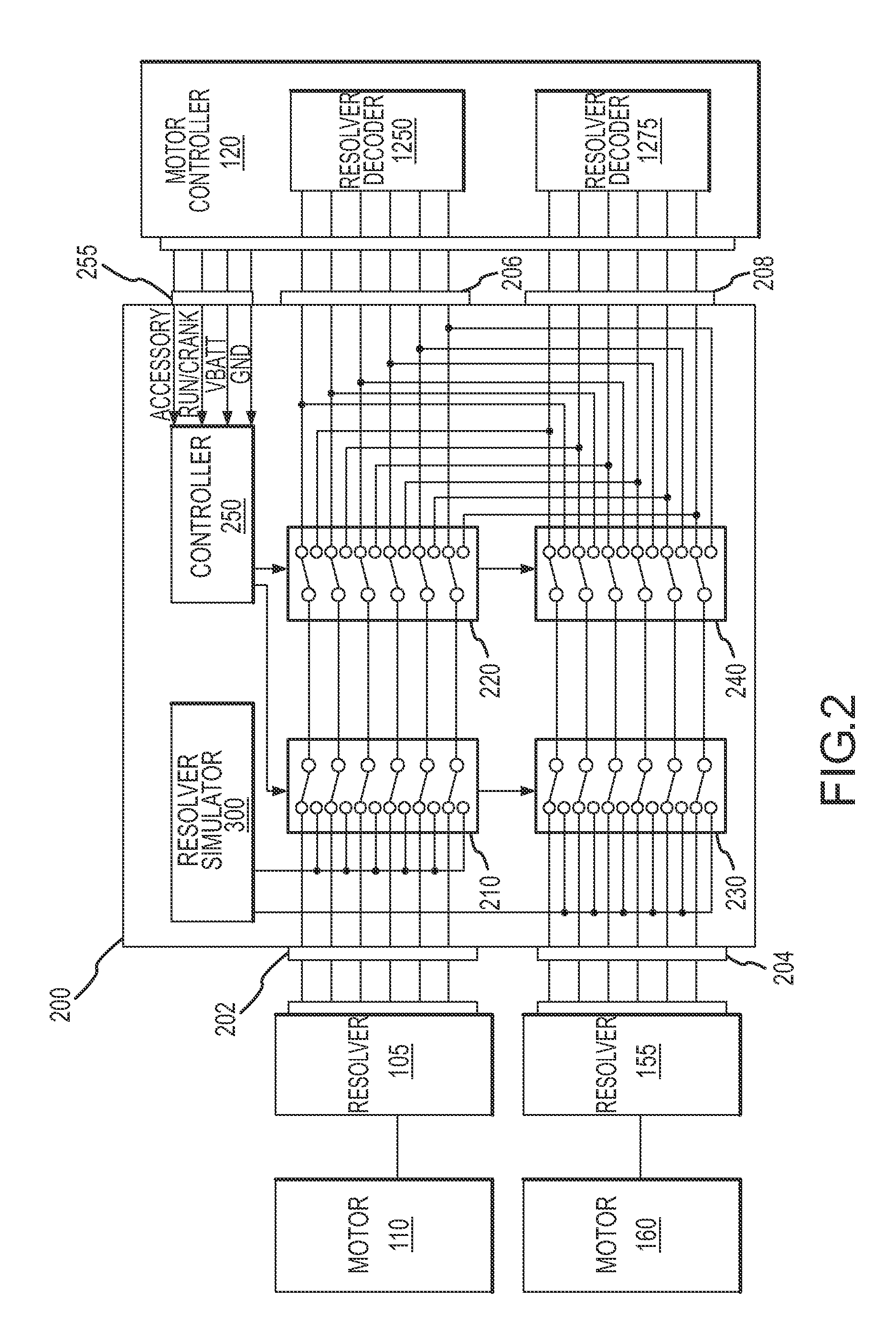
[0017]FIG. 1 is a schematic of a prior art system 10 including a motor-resolver system 100 and a motor-resolver system 150. Motor-resolver system 100 includes a resolver 105 coupled to a motor 110. Resolver 105 is configured to transmit signals representing the operating characteristics (e.g., motor speed, rotor angle, signal strength, connectivity, etc.) of motor 110 to a motor controller 120.

[0018]Similarly, motor-resolver system 150 includes a resolver 155 coupled to a motor 160. Resolver 155 is also configured to transmit signals representing the operating characteristics of motor 160 to motor controller 120.

[0019]Motor controller 120 in...


PUM


Abstract

Apparatus and methods are provided for diagnosing faults in multiple, associated motor-resolver systems. One apparatus includes a swapping circuit coupling a first resolver to a first or second decoder, and a swapping circuit coupling a second resolver to the first or second decoder. One method includes applying a signal from a resolver to a first decoder to determine that the first decoder is malfunctioning if the first decoder continues to generate a fault signal, and applying a signal from a different resolver to a second decoder to determine that a motor associated with the first decoder is malfunctioning if the second decoder generates a fault signal. Another method includes transmitting a signal from a resolver to first and second decoders, transmitting a signal from a different resolver to the first and second decoders, and determining if the first decoder, second decoder, a first motor, or a second motor is malfunctioning.

Description

FIELD OF THE INVENTION[0001]The present invention generally relates to motor-resolver systems, and more particularly relates to apparatus and methods for diagnosing faults in multiple, associated motor-resolver systems.BACKGROUND OF THE INVENTION[0002]Motor-resolver systems are typically employed to accurately sense and control the position of rotating shafts. As a motor is employed to a resolver at a particular rate or rotational velocity, the output of the resolver is then fed to a motor controller to determine if the motor is properly driving the shafts. When a resolver anomaly is detected, the motor controller notifies the user with an error message (e.g., a visual warning, an audio warning, etc.).[0003]Some devices (e.g., a hybrid vehicle) include multiple motors (and multiple resolvers) coupled to a single motor controller. In these devices, the motor controller often includes a resolver decoder for each respective resolver. For example, a hybrid vehicle includes a first motor...

Claims


Application Information

Patent Timeline
Patent Type & Authority Applications(United States)
IPC IPC(8): G05B1/06
CPCG01D3/08G01D18/00H03M1/1071H03M1/485
Inventor FU, DAVID T.WANG, WEI D.
Owner DAIMLER AG
Why Eureka
Try Eureka