Method and Device for Analyzing Distribution of Coercive Force in Vertical Magnetic Recording Medium Using Magnetic Force Microscope

a technology of magnetic force microscope and distribution of coercive force, which is applied in the direction of material magnetic variables, scanning probe techniques, instruments, etc., can solve the problems of difficult condense of magnetic field observing apparatus utilizing the kerr effect, inability to observe magnetic domains at nano-scale resolution, and inability to adapt domains

Inactive Publication Date: 2008-11-20
JAPAN SCI & TECH CORP
View PDF2 Cites 12 Cited by
  • Summary
  • Abstract
  • Description
  • Claims
  • Application Information

AI Technical Summary

Benefits of technology

[0018]a control section which allows the image generating section to generate first magnetic domain image data while allowing the magnetic device to apply the first external magnetic field to the sample, the control section generating second magnetic domain image data while allowing the magnetic device to apply the second external magnetic field to the sample, the control section further allowing the first and second image generating section to hold the first and second image data; and

Problems solved by technology

However, these apparatuses can simply display images of magnetic domains but are not adapted to also display an image of distribution of coercive forces in magnetic domains.
However, it is difficult for the magnetic-field observing apparatus utilizing the Kerr effect to condense the light beam until its beam spot size becomes of the order of nanometers.
Thus, this observing apparatus does not enable magnetic domains to be observed at a nano-scale resolution.
However, the electron microscope basically does not enable measurements in magnetic fields.
This disadvantageously makes it impossible to measure the sample while directly viewing flux reversal at the same position of the sample to determine the nano-scale distribution of coercive forces.
However, most of the researches using the conventional magnetic-force microscope are limited to observations of magnetic domain structures.
In particular, observations of magnetic domains in magnetic fields are limited to relatively low magnetic fields of at most several kOe.

Method used


Image

  • Method and Device for Analyzing Distribution of Coercive Force in Vertical Magnetic Recording Medium Using Magnetic Force Microscope
  • Method and Device for Analyzing Distribution of Coercive Force in Vertical Magnetic Recording Medium Using Magnetic Force Microscope
  • Method and Device for Analyzing Distribution of Coercive Force in Vertical Magnetic Recording Medium Using Magnetic Force Microscope

Examples


Embodiment Construction

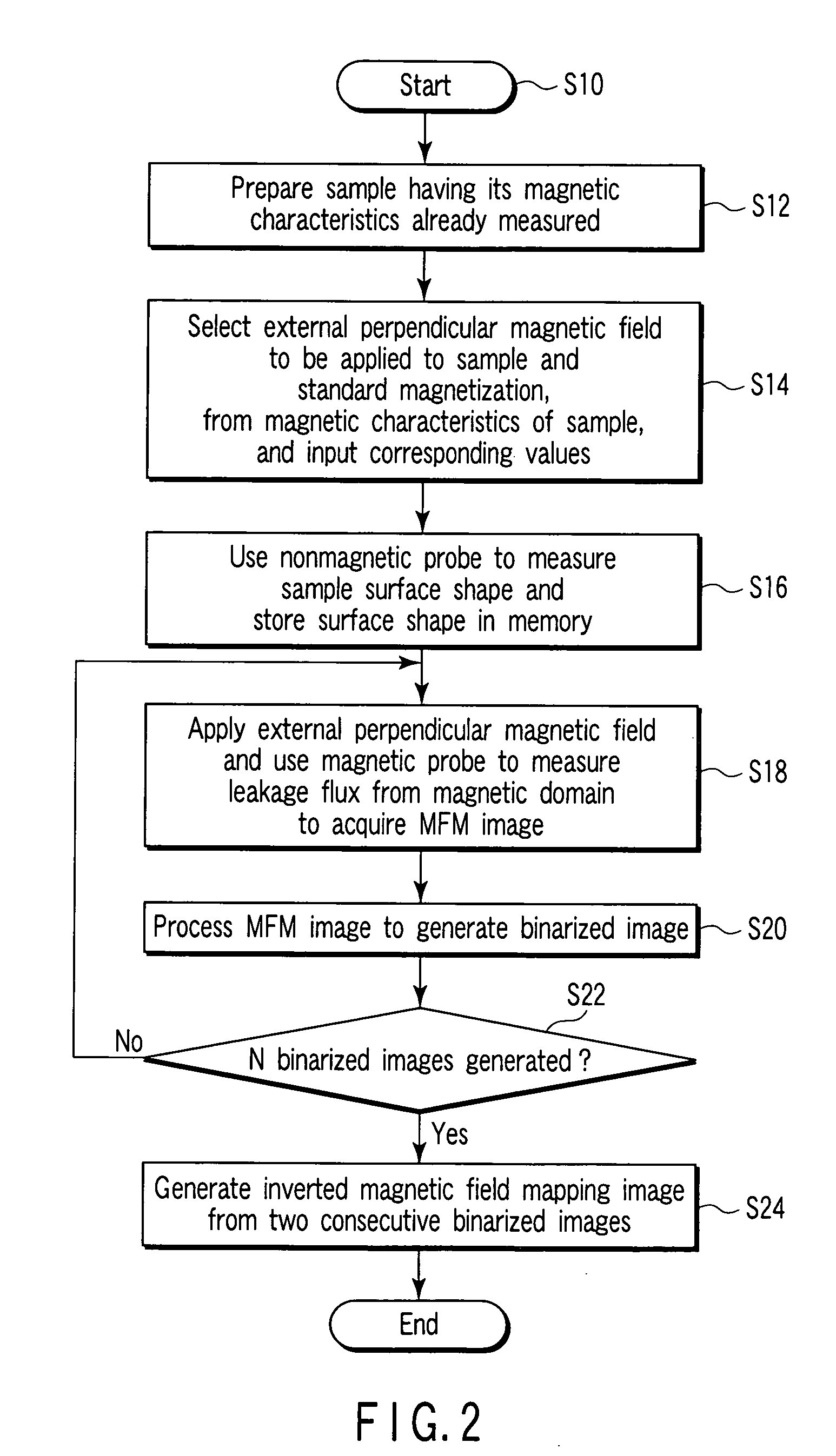
[0035]With reference to the drawings, description will be given of a method for analyzing the distribution of coercive forces in a perpendicular magnetic recording medium utilizing a magnetic-force microscope in accordance with the present invention.

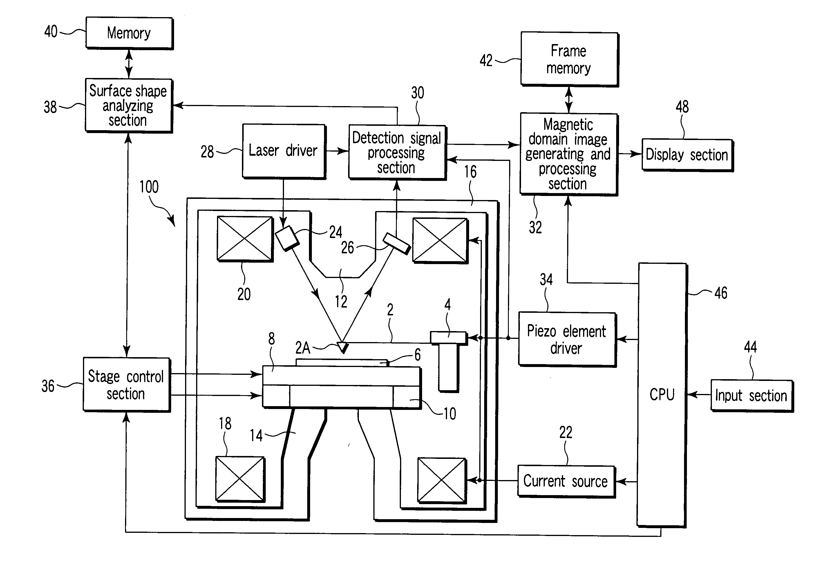
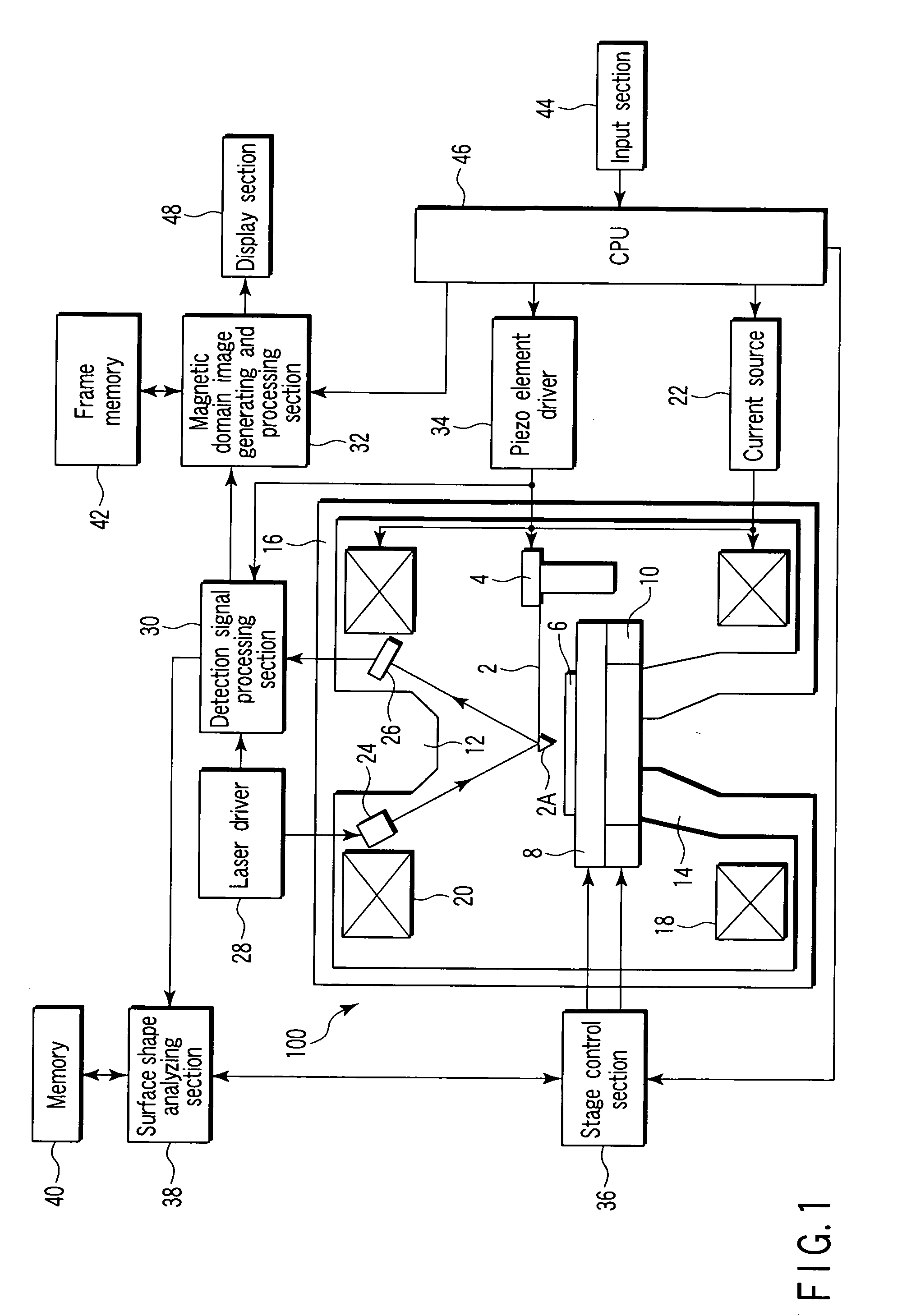
[0036]FIG. 1 is a block diagram showing an analyzing apparatus that analyzes the distribution of coercive forces in a perpendicular magnetic recording medium utilizing a magnetic-force microscope in accordance with the present invention.

[0037]In FIG. 1, reference numeral 100 denotes a magnetic-force microscope having a magnetic field applying function. Reference numeral 2 denotes a cantilever serving as a probing section of the magnetic-force microscope; the cantilever is made of a nonmagnetic substance and has a probe 2A at its free end. The cantilever 2 is vibratorily supported by a piezo element 4, and the probe 2A at the tip of the cantilever is placed on a sample 6. In a magnetic domain observing mode in which the distribution of co...


PUM

PropertyMeasurementUnit
coercive forcesaaaaaaaaaa
magnetic fieldaaaaaaaaaa
magnetizationaaaaaaaaaa

Abstract

In a coercive force distribution analysis device, a magnetic field is applied in substantially vertical direction to a sample having a magnetic thin film capable of recording vertical magnetism. A magnetic flux detection signal is generated in accordance with the leaking magnetic flux generated from a magnetic domain of the sample surface while the sample is horizontally moved. A first and a second external magnetic field corresponding to a first and a second threshold value selected from hysteresis characteristic corresponding to the sample average magnetization are applied to the sample so as to generate image data on a first and a second magnetic domain. The first and the second image data are subjected to digitization processing by the first and the second threshold value and the difference between them is generated as a first coercive force distribution pattern.

Description

TECHNICAL FIELD[0001]The present invention relates to methods for analyzing the distribution of coercive forces in a perpendicular magnetic recording medium utilizing a magnetic-force microscope, and analyzing apparatuses for the methods, and in particular, to analyzing methods of analyzing image outputs from the magnetic-force microscope to display an image of distribution of coercive forces in the perpendicular magnetic recording medium, and analyzing apparatuses for the methods.BACKGROUND ART[0002]Conventionally known apparatuses that observe magnetic domains and display their images include magnetic-field observing apparatuses utilizing a magnetic Kerr effect, scanning electron microscopes (spin polarized SEM), and transmission electron microscopes. However, these apparatuses can simply display images of magnetic domains but are not adapted to also display an image of distribution of coercive forces in magnetic domains.[0003]The magnetic-field observing apparatus utilizing the K...

Claims


Application Information

Patent Timeline
Patent Type & Authority Applications(United States)
IPC IPC(8): G01R33/00G01N27/72G01Q20/02G01Q30/04G01Q60/50G01R33/02G11B5/84
CPCB82Y15/00B82Y25/00B82Y35/00G01Q60/50G01Q60/56G01R33/10G01R33/14
Inventor ISHIO, SHUNJISAITO, HITOSHI
Owner JAPAN SCI & TECH CORP
Why Eureka
Try Eureka