
Determination of Field Distribution

a field distribution and distribution technology, applied in the direction of scanning probe techniques, photomechanical devices, instruments, etc., can solve the problems of neglected influence of substrates on the distribution of filed, difficult to implement industrial applications, etc., and achieve the effect of improving field convergence and reducing field summation orders

Inactive Publication Date: 2008-11-20
AGENCY FOR SCI TECH & RES
View PDF3 Cites 4 Cited by
  • Summary
  • Abstract
  • Description
  • Claims
  • Application Information

AI Technical Summary

Benefits of technology

[0018]The transformation of scattered field transformation may remove a matrix inversion operation in determining a Weyl-type reflection matrix. The transformation of scattered field may reduce field summation orders and may improve field convergence.

Problems solved by technology

However, this approach is difficult to implement in an industrial application due to sophisticated hardware to control the near-field distance and low throughout.
The limitation of the majority of previous systems used for determining the intensity of the filed distribution is the use of conventional Mie theory for theoretical modeling, and thus the influence of the substrate on the filed distribution is neglected.

Method used


Image

  • Determination of Field Distribution
  • Determination of Field Distribution
  • Determination of Field Distribution

Examples


Embodiment Construction

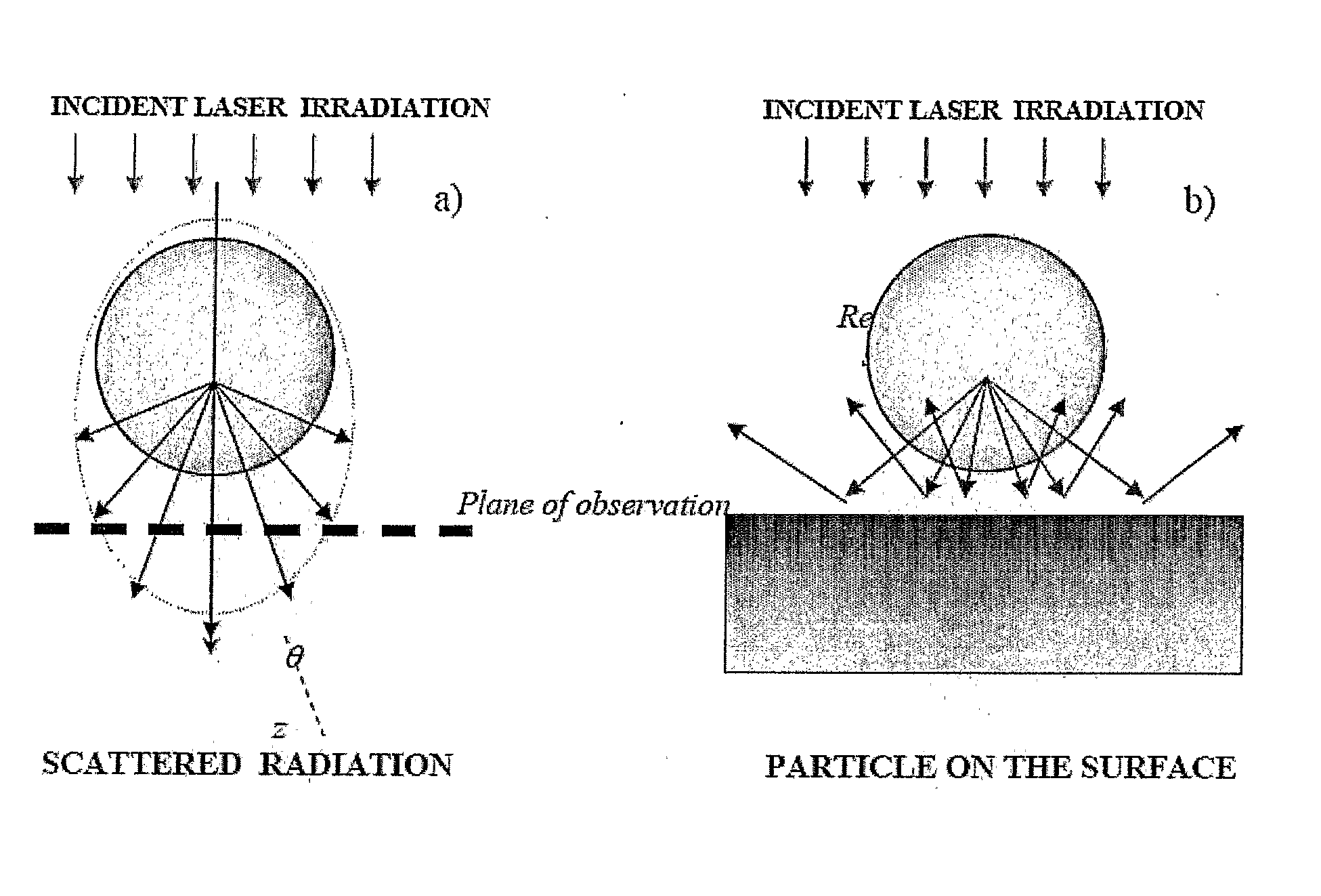
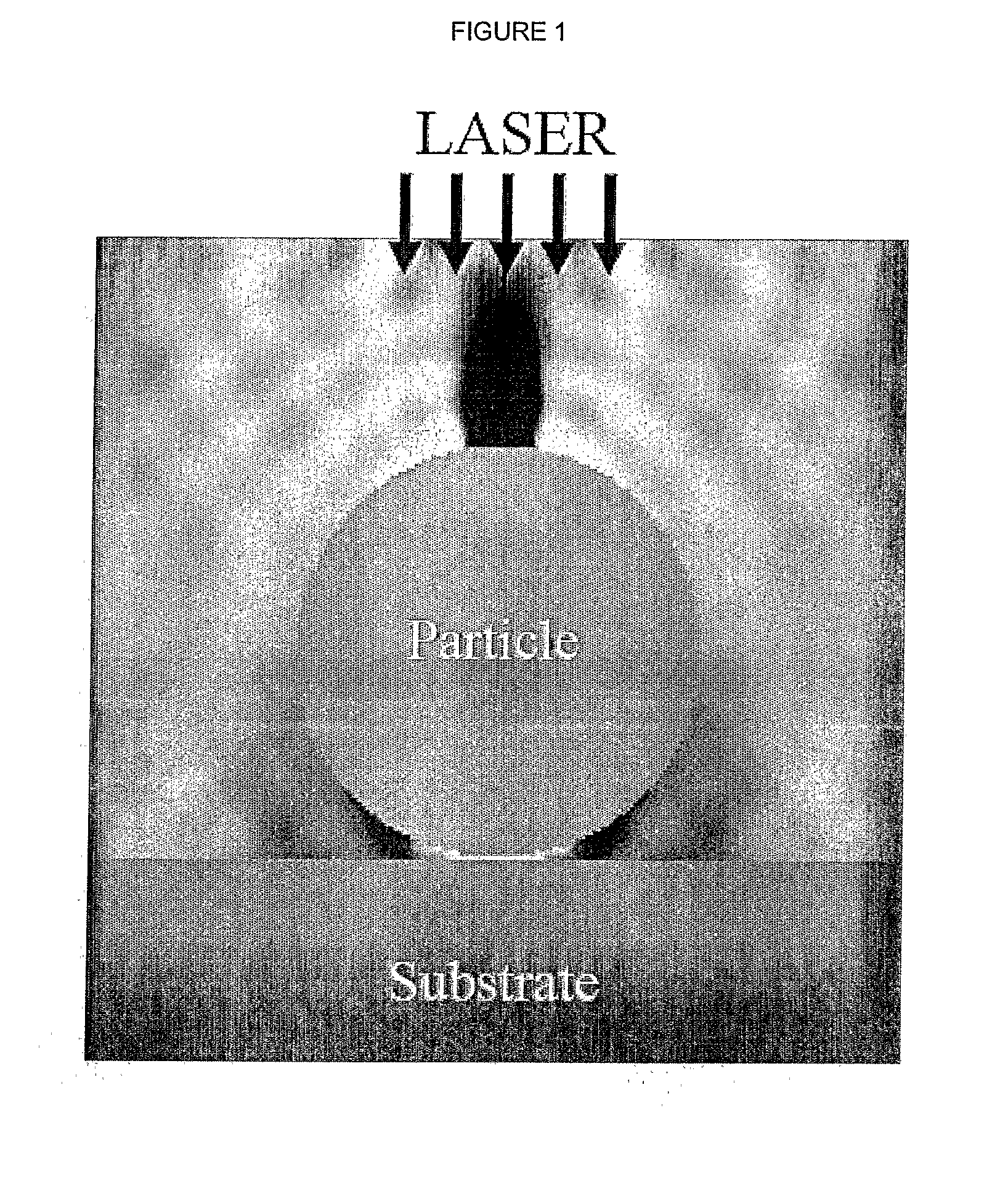
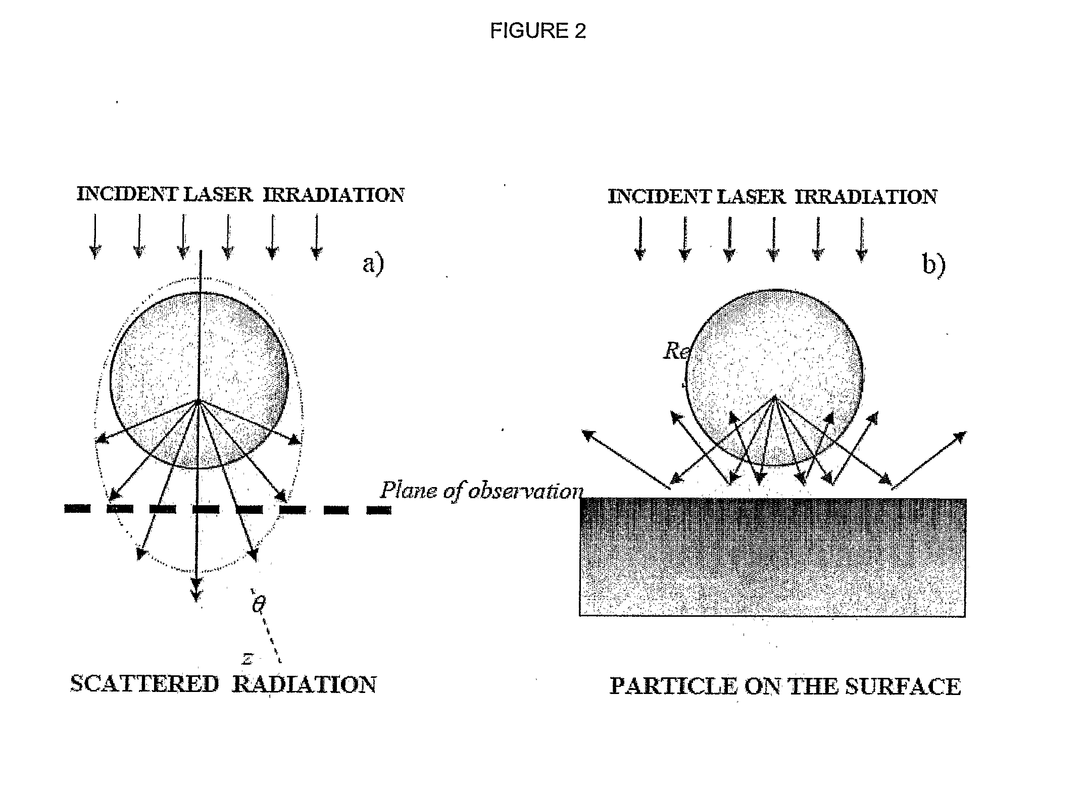
[0030]The method is to determine the distribution of fields and Poynting vector according to Particle on Surface theory. The method takes into account the secondary scattering of radiation reflected from the substrate, as is shown in FIG. 1.

[0031]The intensity distribution (z-component of the Poynting vector) is within the x-z plane for radiation with λ=248 nm, scattered by polystyrene particle (n=1.6, a=0.5 μm) on Si surface. Gradations of the intensity are given from negative (dark) to positive (light) values. The dark area on the top of the particle corresponds to energy flux directed up, while the white area under the particle corresponds to energy flux directed to the substrate.

[0032]Many peculiarities of the scattering process can be understood on the basis of the Mie theory, where the particle is considered as a sphere.

[0033]The amplitude of the electric vector of the incident plane wave is normalized to unity, and the wave propagates along the z-coordinate (positive directio...


PUM


Abstract

A method for determining field intensity for a particle on a substrate, the method comprising providing an incident wave, determining an electric vector of the field and a magnetic vector of the field inside and outside of the particle, and determining additional scattered fields inside and outside of the particle due to reflection of the incident wave from the substrate.

Description

FIELD OF THE INVENTION[0001]This invention relates to the determination of field distribution and refers particularly, though not exclusively, to a method for the determination of field distribution inside and outside a particle, particularly with a spherical particle on surface.BACKGROUND OF THE INVENTION[0002]Laser-induced near-field patterning of surface at a resolution far below the diffraction limit has attracted more and more attention in recent years due to its extensive potential applications in high-density storage and high-resolution optical lithography for nanodevice fabrication. In most near-field techniques, the subwavelength resolution is achieve by placing a small aperture between the recording medium and light source. If the aperture-to-medium separation is controlled at a distance much smaller than the wavelength, the resolution will be determined by the aperture size instead of the diffraction limit. This technique is used in the scanning near-field optical microsc...

Claims


Application Information

Patent Timeline
IPC IPC(8): G01R33/02G01N13/14G01Q30/04G01Q60/18
CPCB82Y20/00B82Y35/00G03F7/2014G01Q60/18G01Q30/04
Inventor WANG, ZENGBOLUKIYANCHUK, BORIS
Owner AGENCY FOR SCI TECH & RES
Learn More