Method for determining a switch-on threshold and electronic circuit arrangement for carrying out the method

a switch-on threshold and electronic circuit technology, applied in logic circuit coupling/interface arrangements, pulse techniques, instruments, etc., can solve the problems of high current, high power loss, high susceptibility of circuit arrangement to interference, etc., and achieve low input impedance of electronic circuit arrangement, high input current, and low power loss

Inactive Publication Date: 2008-11-20
ABB TECH AG
View PDF7 Cites 15 Cited by
  • Summary
  • Abstract
  • Description
  • Claims
  • Application Information

AI Technical Summary

Benefits of technology

[0010]One aspect of the disclosure relates to changing over the input impedance of an electronic circuit arrangement in such a way that a switch-on instant can be detected without interference, and that a high power loss due to an excessively high input current is at the same time avoided. An excessively high input current is avoided by changing over the input impedance at a further instant, which lies after a delay time duration after the switch-on instant.
[001

Problems solved by technology

One essential disadvantage of conventional circuit arrangements is that high input impedances result in the circuit arrangement having a high susceptibility to interference.
This leads to high currents and thus to high power losses in an inexpedient manner in the case of the input voltage ranges considered (80 V-300 V).
Although the reduction of the input impedance lessens somewhat the

Method used


Image

  • Method for determining a switch-on threshold and electronic circuit arrangement for carrying out the method
  • Method for determining a switch-on threshold and electronic circuit arrangement for carrying out the method

Examples


Embodiment Construction

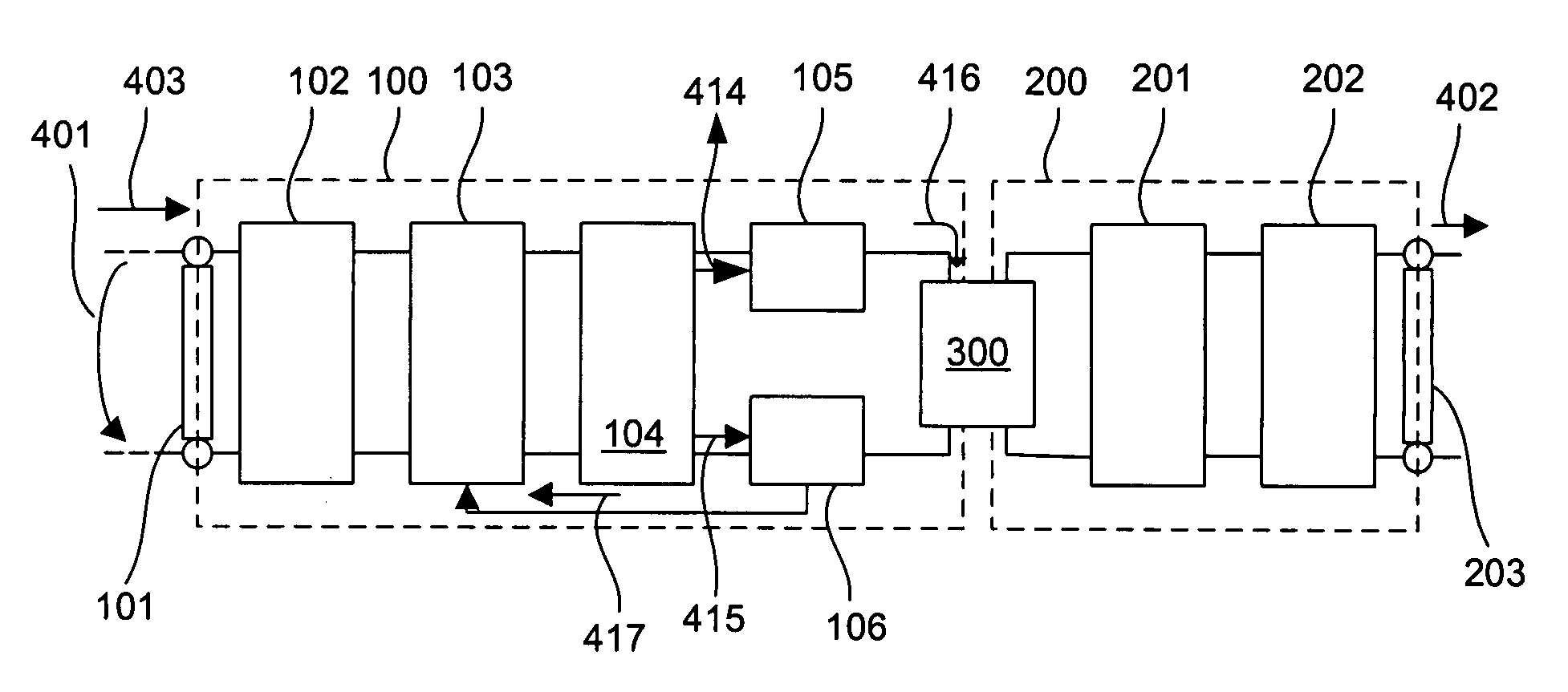
[0035]FIG. 1 shows a schematic block diagram of an electronic circuit arrangement for converting an input voltage signal into an output signal in accordance with one exemplary embodiment of the present disclosure. As shown in FIG. 1, a primary-side circuit device 100 is connected to a secondary-side circuit device 200 via a coupler device 300.

[0036]The coupler device 300 may be formed as an optocoupler or as a GMR coupler (Giant Magnetic Resistance coupler). An input voltage signal 401 to be processed is applied to the primary-side circuit device 100, said input voltage signal leading to an input current 403 into the circuit arrangement. An input unit 101 serves for inputting the input voltage signal 401 and the input current 403.

[0037]The input signals are firstly fed to a primary-side filter unit 102, which filters out coarse interference of the input voltage signal. An exemplary element of the electronic circuit arrangement according to the disclosure is an input impedance change...


PUM


Abstract

An electronic circuit arrangement is disclosed for converting an input voltage signal having a first voltage level into an output signal having a second voltage level. An input unit is provided for inputting the input voltage signal at the first voltage level, while an output unit is arranged for outputting the output signal at the output of the electronic circuit arrangement. A threshold value comparison unit serves for comparing the first voltage level of the input signal with a switch-on threshold value. The circuit arrangement furthermore contains an input impedance changeover unit for changing over an input impedance of the circuit arrangement from a low value to a high value after a predetermined delay duration after the first voltage level of the input voltage signal exceeded the switch-on threshold value.

Description

RELATED APPLICATIONS[0001]This application claims priority under 35 U.S.C. §119 to EP Application 06405407.5 filed in Europe on Sep. 28, 2006, the entire contents of which are hereby incorporated by reference in their entireties.TECHNICAL FIELD[0002]Electronic circuit arrangements are disclosed for converting input signals into output signals, e.g., an electronic circuit arrangement into which is input a digital input signal which changes over into a digital output signal upon reaching a specific switching threshold.[0003]Specifically, the present disclosure relates to an electronic circuit arrangement for converting an input voltage signal having a first voltage level into an output voltage signal having a second voltage level, provision being made of an input unit for inputting the input voltage signal at the first voltage level, a threshold value comparison unit for comparing the first voltage level of the input signal with a switch-on threshold value, and an output unit for outp...

Claims


Application Information

Patent Timeline
IPC IPC(8): H03L5/00
CPCH03K3/02337H03K5/084H03K2217/0036H03K17/78H03K17/691G05F1/00
Inventor SCHILLING, ROBERT
Owner ABB TECH AG
Why Eureka
Try Eureka