Backlight Device

a backlight device and color technology, applied in the field of backlight devices, can solve the problems of low uniformity in luminance, undesirable light emission characteristics of backlight devices, etc., and achieve the effect of reducing the production cost of backlight devices and generating variations in luminance or chromaticity

Inactive Publication Date: 2008-11-20
SONY CORP
View PDF18 Cites 41 Cited by
  • Summary
  • Abstract
  • Description
  • Claims
  • Application Information

AI Technical Summary

Benefits of technology

[0007]It is therefore an object of the present invention to solve the above problem and to provide a backlight device which, even in case a light source is constituted with the use of light emitting diodes, suffering from variations in chromaticity and luminance, to avoid wasteful non-use of the light emitting diodes fabricated and available on the market, radiates white light free from variations in chromaticity or luminance, and which may be used satisfactorily as the illuminating light for the color liquid crystal display panel.
[0014]According to the present invention, in which light emitting diode units are arrayed to satisfy a chromaticity-based arraying policy and a luminance-based arraying policy, light emitting diode units, manufactured but not used, may be used to advantage without generating variations in luminance or chromaticity. It is therefore possible to reduce production costs of a backlight device color for illuminating a liquid crystal display panel and hence a color liquid crystal display apparatus including a color liquid crystal display panel and a backlight device.

Problems solved by technology

For this reason, if the light emitting diodes, available on the market, are used at random to constitute a light source for a backlight device, the result is a backlight device exhibiting undesirable light emitting characteristics, such as low uniformity in chromaticity (severe chromaticity variations) or low uniformity in luminance (severe luminance variations).

Method used


Image

  • Backlight Device
  • Backlight Device
  • Backlight Device

Examples


Embodiment Construction

[0034]Referring to the drawings, preferred embodiments of the present invention will be described in detail. It should be noted that the present invention is not to be limited to the embodiments now described and may be optionally modified without departing from the scope of the invention.

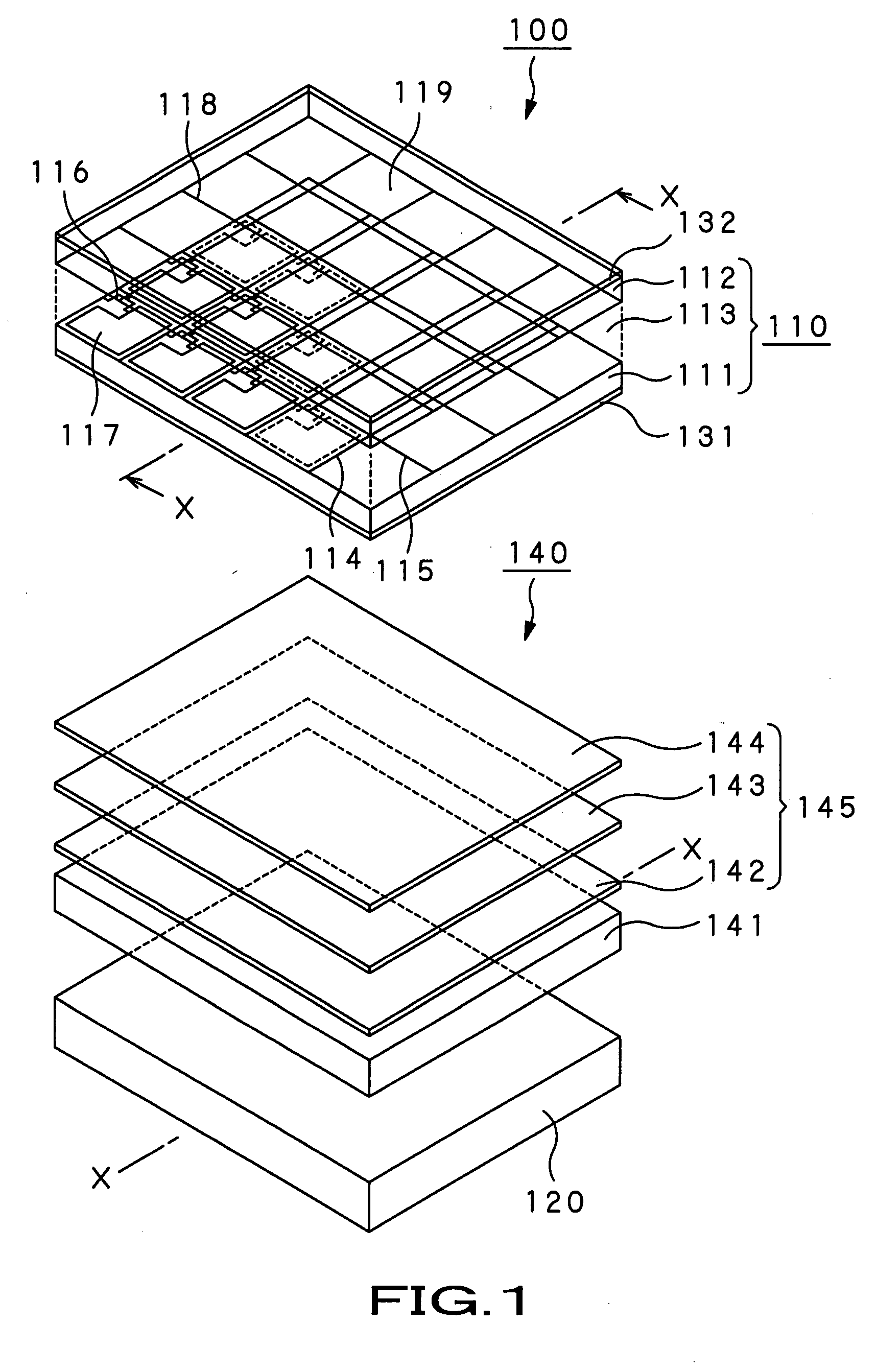
[0035]The present invention is applied to, for example, a color liquid crystal display apparatus 100 arranged as shown in FIG. 1.

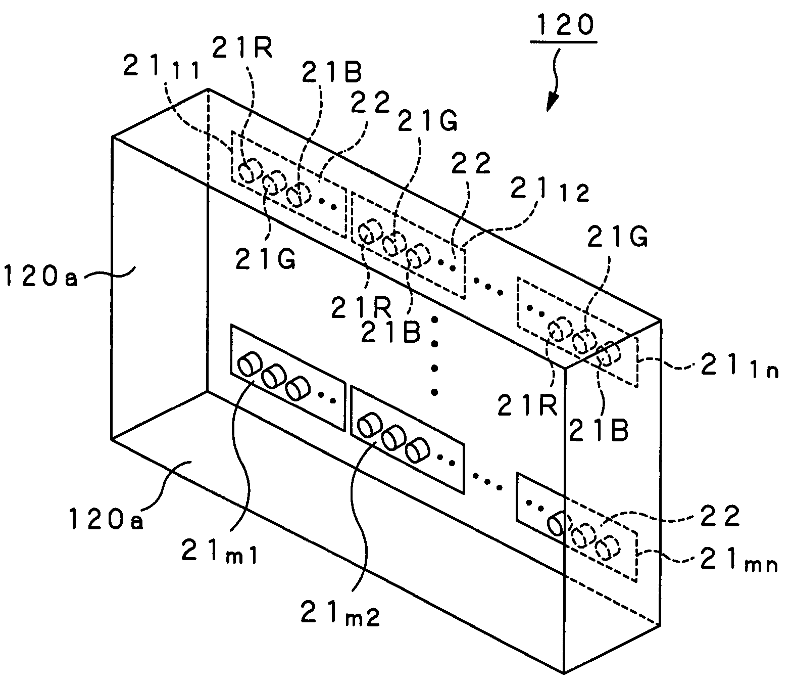
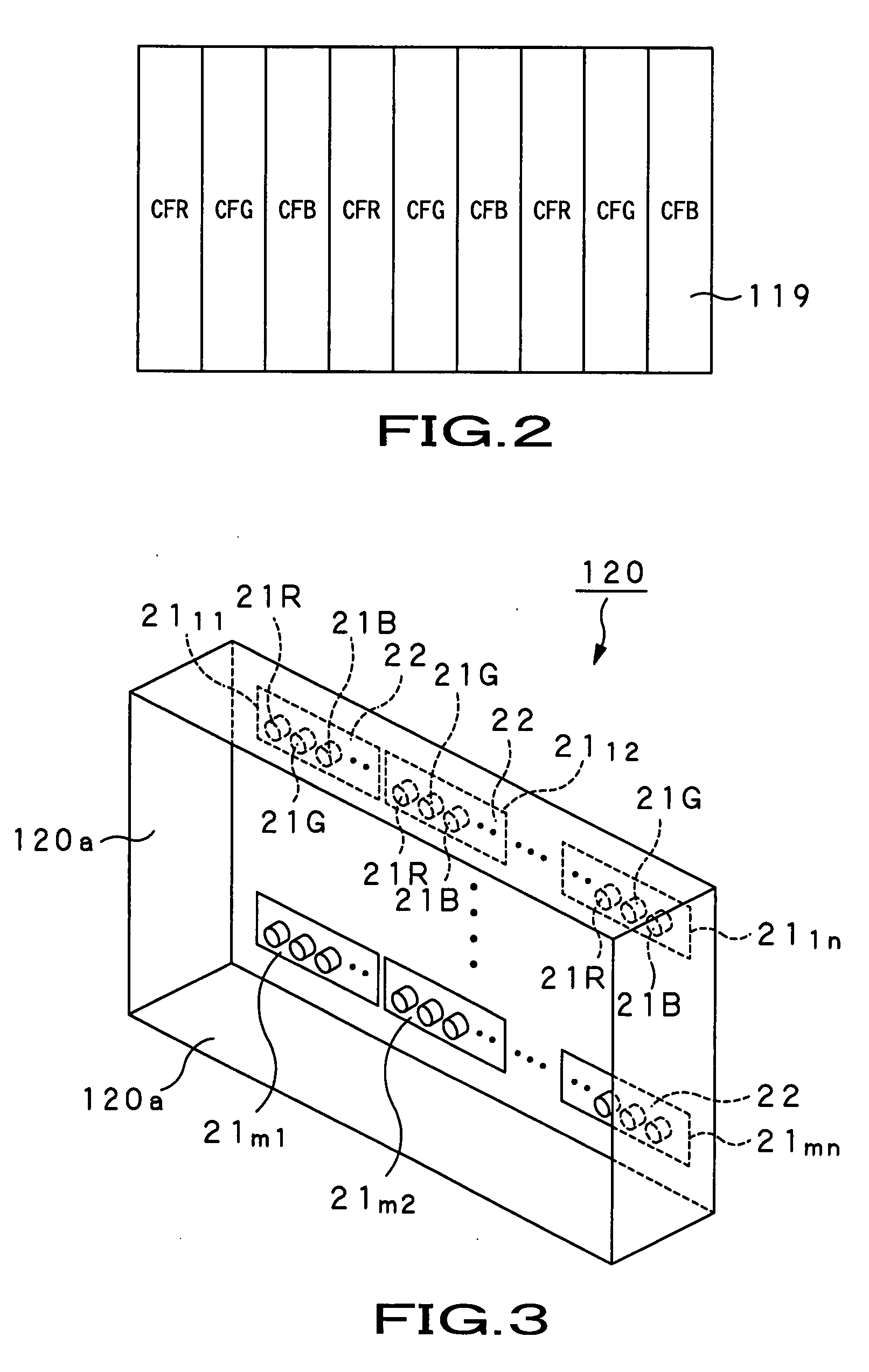
[0036]In this figure, the transmissive color liquid crystal display apparatus 100 is made up of a transmissive color liquid crystal display panel 110, and a backlight unit 140, provided on the backside of this color liquid crystal display panel 110. This transmissive color liquid crystal display apparatus 100 may be provided with a receiving unit, such as an analog tuner or a digital tuner, for receiving the ground wave or the satellite wave, a picture signal processing unit or an audio signal processing unit for processing picture signals or audio signals, received by th...


PUM


Abstract

Disclosed is a backlight device for illuminating a transmissive color liquid crystal display panel from its backside with white light. The backlight device includes, as a light source, a plural number of principal light emitting diode units 21mn, and a plural number of subsidiary light emitting diode units 21mn, where m and n are natural numbers. Each principal light emitting diode unit is made up by a plural number of light emitting diodes (21) arrayed in a string and emits white light of preset chromaticity. Each subsidiary light emitting diode unit is made up by a plural number of light emitting diodes (21) arrayed in a string and emits white light of chromaticity in the vicinity of the preset chromaticity. The number of the subsidiary light emitting diode units is smaller than that of the principal light emitting diode units. When the principal light emitting diode units and the subsidiary light emitting diode units are arrayed in a two-dimensional matrix, the subsidiary light emitting diode units 21mn are arrayed without being juxtaposed on the same row, and the subsidiary light emitting diode units 21mn, arrayed in a center column of the two-dimensional matrix, are arrayed towards the center of a color liquid crystal display panel (110).

Description

TECHNICAL FIELD[0001]This invention relates to a backlight device for illuminating a color liquid crystal display panel. More particularly, it relates to a backlight device in which a number of light emitting diode units, used as a light source for the backlight device, and which emit white light exhibit variations in chromaticity and luminance, are properly arrayed such as to suppress the variations in chromaticity and luminance.[0002]The present application claims priority rights on the basis of the Japanese Patent Application 2004-325661, filed in Japan on Nov. 9, 2004. The contents of these Patent Applications are to be incorporated by reference in the present application.BACKGROUND ART[0003]A TV receiver of an extremely thin thickness, such as one employing a liquid crystal display (LCD) or a plasma display panel (PDP), has been developed and put to practical use to take the place of a TV receiver employing a cathode ray tube (CRT) which has long been used since the start of TV...

Claims


Application Information

Patent Timeline
Patent Type & Authority Applications(United States)
IPC IPC(8): F21V9/00
CPCG02F1/133603G02F1/133611G02F1/133609G02F1/133608G02F1/1335
Inventor OKU, TAKASHIARAI, TAKEOOTA, YUTAKATAGAWA, YASUHIRO
Owner SONY CORP
Why Eureka
Try Eureka