
Led Lamp

a technology of led lamps and led light sources, which is applied in the direction of point-like light sources, semiconductor devices for light sources, light and heating apparatus, etc., can solve the problems of not being able to assist led lighting sources, plastics are not good heat emission materials, and glass adds to the weight of lamps

Inactive Publication Date: 2008-11-20
CHAN KK
View PDF23 Cites 5 Cited by
  • Summary
  • Abstract
  • Description
  • Claims
  • Application Information

AI Technical Summary

Benefits of technology

[0004]Therefore, an object of the invention is to provide a kind of LED lamp, which has a metal lamp-cup with electroplated reflecting film and LEDs that are arranged in a semi-sphere. It is characterized in strong light reflection, large luminous flux and a wide light emitting angle.
[0009]In another other aspect of the invention, the metal lamp-cup has a much larger area made of metal or other heat conductive materials. The inner surface of the lamp-cup is electroplated or welded with reflecting film. Thus, light from the LEDs is reflected by the reflecting film, and the light is brighter and more equitably distributed. The metal lamp-cup with inner reflecting film resolves the heat-emitting issue of high luminous flux LEDs, facilitating both light and heat emission of the LED lamp.
[0010]On Sep. 1, 2004, the applicant applied for a utility patent (number: 200420093010.6) and PCT, titled LED lamp, in which the astigmatism plate can be implemented with the invention. The astigmatism plate is made of transparent or subtransparent materials, such as, colophony, etc. The plate has the same number of holes as that of LEDs and they are integrated into one entity so that the light of the LEDs is radiated or scattered in various directions, increasing the light emitting angle of the LEDs.
[0011]In another aspect of the invention, the lamp-lid is made of transparent or subtransparent material, the lamp-lid and lamp-cup have the same number and position of holes, through which, the lamp-lid and lamp-cup can be secured tightly by bolts and nuts to avoid loosening. This resolves the heat-aging issue of a glued border between lamp-lid and lamp-cup. And, because of the large reflection area of the lamp-cup and the space between the lamp-lid and the LEDs, the light from the LEDs can be effectively and uniformly reflected and emitted.
[0013]Because of the semi-spheric arrangement of LEDs and / or the integration of the astigamatism plate and the LEDs, and the large area metal lamp-cup with a reflecting film, a more uniform and efficient lighting source is achieved the heat-emitting issue of high luminous flux LEDs is minimized.

Problems solved by technology

In conventional LED lamps, most lamp-cups were made of glass or plastics, which are not good heat emission materials.
Moreover, glass adds to the weight to the lamp, while it cannot assist the LED lighting sources.
Also conventional LED lamps are arranged in the same level in a matrix and the transparent lamp-lid is typically close to the LEDs, both of which may hinder the ability to emit light.

Method used


Image

  • Led Lamp
  • Led Lamp
  • Led Lamp

Examples


Embodiment Construction

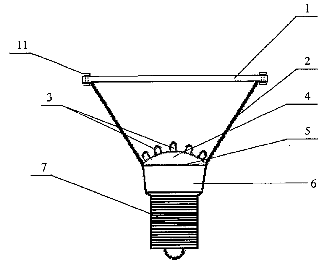
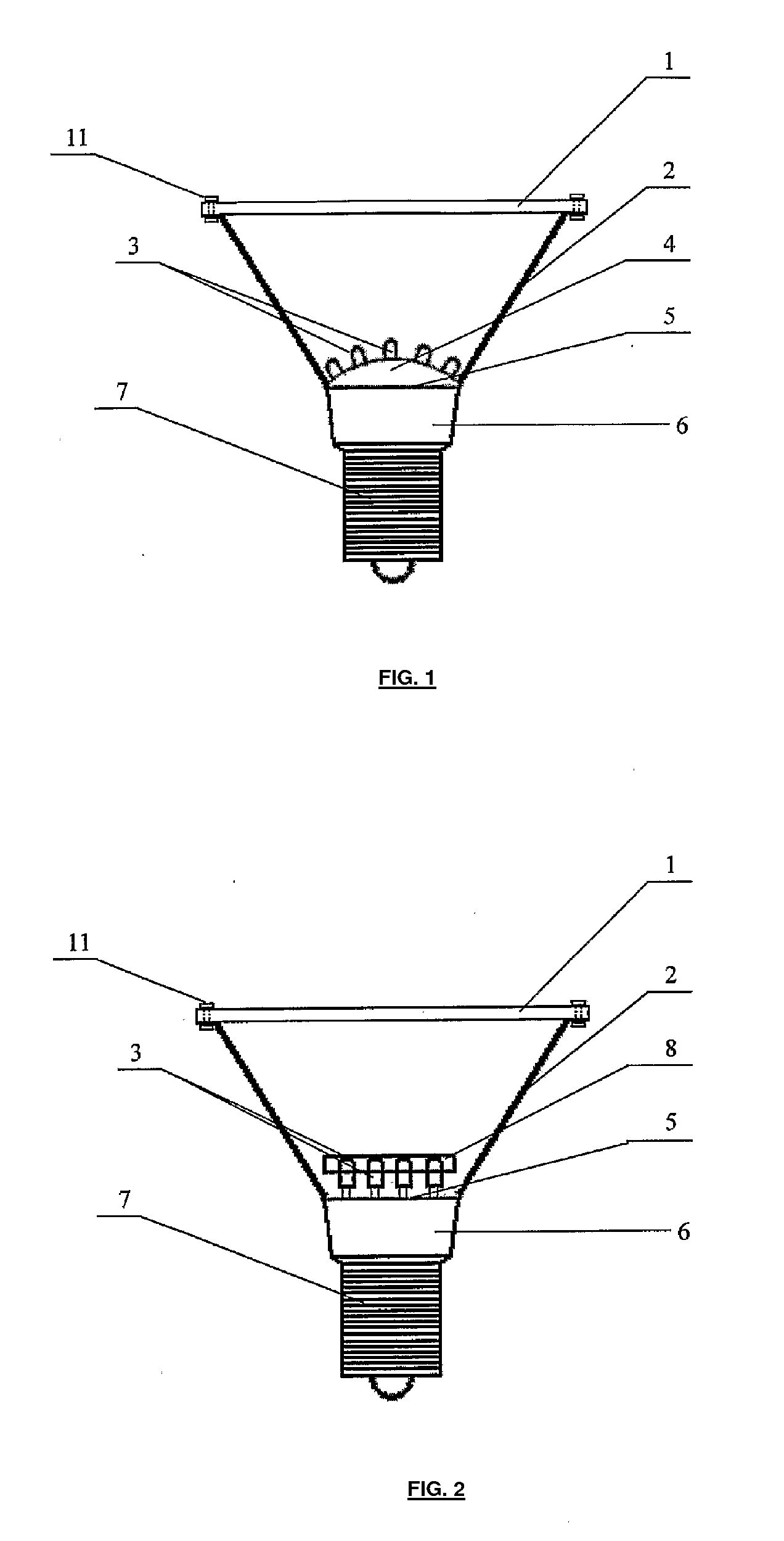
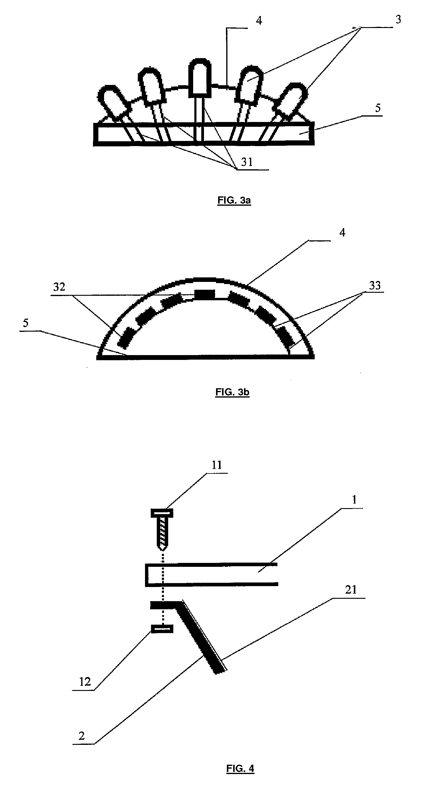
[0019]FIG. 1 shows a lamp-lid (1); metal lamp-cup (2); an insulating layer (6) for connecting a lamp-cap (7) and the metal lamp-cup (2); and LEDs (3), a semispherical pallet (4), and printed circuit board (PCB) (5) in the metal lamp-cup (2); characterized in that a semi-spherical pallet (4) is provided on the PCB (5), the semispherical pallet (4) has the same number of holes as that of the LEDs (3), the LEDs (3) are installed in the holes; and electrical connections (31) of the LEDs are connected to the PCB (5) through the semispherical pallet (4). The LEDs (3) installed in this way are mounted on the semispherical pallet (4) and arranged in a semisphere. Thus, light of the LEDs (3) is radiated in various directions, increasing the light emitting angle of the LEDs.

[0020]FIG. 3 is a perspective view of LEDs (3) interconnected with the semispherical pallet (4). As shown in FIG. 3b, while the semispherical pallet is made of transparent or subtransparent materials and the LED chips (32)...


PUM


Abstract

An LED lamp includes a lamp-lid, a metal lamp-cup, an insulating layer for connecting a lamp-cap and the metal lamp-cup, LEDs, a semispherical pallet or an astigmatism plate, and a PCB (Printed Circuit Board) in the metal lamp-cup, characterized in that, one semispherical pallet is provided on said PCB, the semispherical pallet has the same number of holes as that of the LEDs, the LEDs are installed in the holes of the semispherical pallet, electrical connections of the LEDs are connected to the PCB through the semispherical pallet, and provided with power. The LEDs installed in this way are mounted on the semispherical pallet and arranged in a semisphere, thus light of the LEDs is radiated in various directions, increasing the light emitting angle of the LEDs, or the semispherical pallet is replaced by the astigmatism plate made of transparent or subtransparent material, the said metal lamp-cup is a larger area lamp cup made of metal or heat conduct materials; thus facilitating the heat emission of the LED lamp.

Description

CROSS-REFERENCE TO RELATED APPLICATION[0001]This application is a U.S. national phase entry of international application number PCT / CN2005 / 001562 with international filing date of Sep. 26, 2005 and claims priority to Chinese application serial number 200410078393.4 filed on Sep. 27, 2004.TECHNICAL FIELD[0002]This invention relates to LED lamp and more particularly to a lamp, which has metal lamp-cup with electroplated reflecting film and LEDs are arranged in semi-sphere.BACKGROUND ART[0003]LEDs (light-emitting diode) have advantages such as very long life times, lighting-efficiency, zero radiation, vibration-proof and low power consumption. Because it is power saving, green and environmentally beneficial over other lighting sources, more and more lamps use LED lighting sources. In conventional LED lamps, most lamp-cups were made of glass or plastics, which are not good heat emission materials. Moreover, glass adds to the weight to the lamp, while it cannot assist the LED lighting so...

Claims


Application Information

Patent Timeline
Patent Type & Authority Applications(United States)
IPC IPC(8): F21V23/00
CPCF21Y2101/02F21K9/137F21V17/12F21Y2111/004F21K9/233F21Y2115/10F21Y2107/20
Inventor CHAN, SZE KEUN
Owner CHAN KK
Learn More