Image encoding apparatus and decoding apparatus, and control method thereof

a technology of encoding apparatus and decoding apparatus, applied in the field of image encoding and decoding techniques, can solve the problems of complicated manipulation of data to fall within a predetermined code size, difficult to achieve random access and rotation processing of respective blocks,

Active Publication Date: 2008-11-20
CANON KK
View PDF11 Cites 12 Cited by
  • Summary
  • Abstract
  • Description
  • Claims
  • Application Information

AI Technical Summary

Benefits of technology

[0019]According to the present invention, pixels as a source of high frequency components such as characters, line arts, and the like can be maintained

Problems solved by technology

However, since the related art uses predictive encoding or variable-length encoding as encoding, encoded data can only be decoded in the same order as that upon encoding, and it is very difficu

Method used


Image

  • Image encoding apparatus and decoding apparatus, and control method thereof
  • Image encoding apparatus and decoding apparatus, and control method thereof
  • Image encoding apparatus and decoding apparatus, and control method thereof

Examples


first embodiment

Modification of First Embodiment

[0082]An example of implementing the first embodiment by a computer program will be described below as a modification of the first embodiment.

[0083]FIG. 5 is a block diagram showing the arrangement of an information processing apparatus (e.g., a personal computer) according to this modification.

[0084]In FIG. 5, reference numeral 1401 denotes a CPU, which controls the overall apparatus using programs and data stored in a RAM 1402 and ROM 1403, and executes application programs of image encoding processing and decoding processing to be described later. Reference numeral 1402 denotes a RAM which comprises an area for storing programs and data which are read out from an external storage device 1407 or storage medium drive 1408, or are downloaded from an external apparatus via an I / F 1409. The RAM 1402 also comprises a work area used when the CPU 1401 executes various kinds of processing. Reference numeral 1403 denotes a ROM which stores a boot program, an...

second embodiment

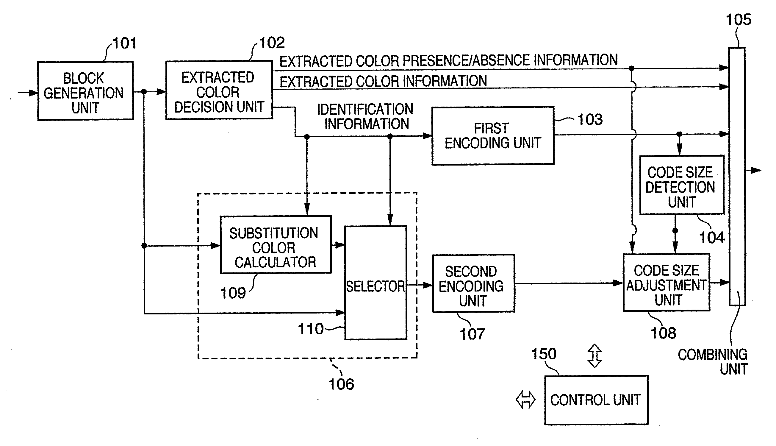
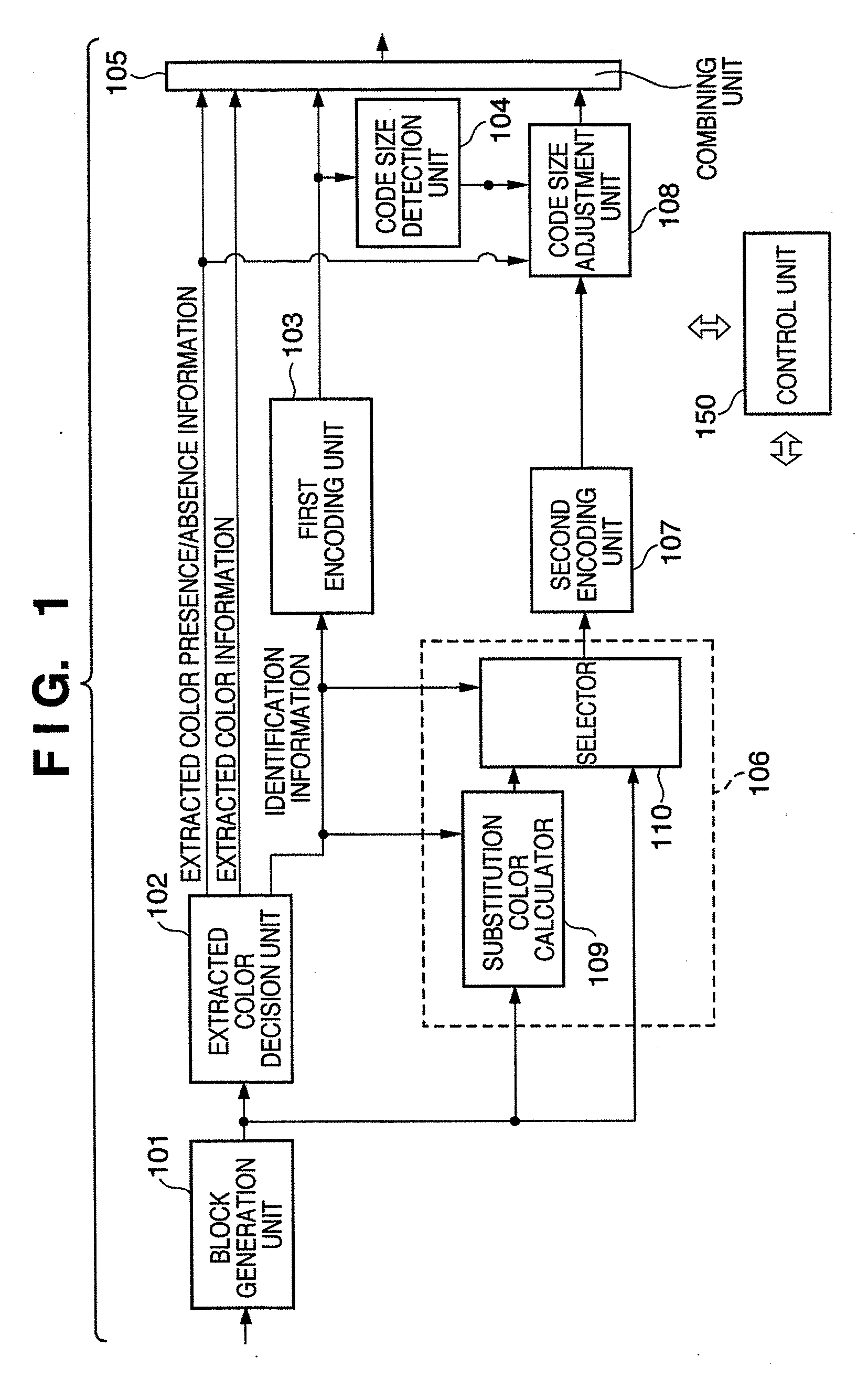
[0120]FIG. 8 is a block diagram showing the arrangement of an encoding apparatus according to the second embodiment. The differences between FIGS. 8 and 1 are that a resolution converting unit 120 is inserted between a substitution unit 106 and second encoding unit 107, and a block generation unit 101 extracts image data of 16×16 pixels from image data to be encoded. Since other components are the same as those in FIG. 1, they are denoted by the same reference numerals, and a detailed description thereof will not be repeated.

[0121]Note that since one block size is 16×16 pixels, an extracted color decision unit 102 generates identification information of 256 bits (=16×16).

[0122]The resolution converting unit 120 converts halftone image data of 16×16 pixels outputted from a selector 110 to have 1 / 2 resolutions in both the horizontal and vertical directions, thereby generating image data of 8×8 pixels. The resolution conversion itself can use a state-of-the-art technique. For example, ...


PUM


Abstract

This invention maintains pixels as a source of a high frequency component such as a character and generates the encoded data having a fixed length for one block. A block generator reads out image data of one block from image data. An extractor extracts a color of a pixel having high frequency component, and generates information identifying pixels of the extracted color and those of non-extracted color. A first encoder lossless-encodes the identification information. A detector detects the data size of the generated encoded data. A substitution unit calculates the average value of colors of the pixels having the non-extracted color, substitutes the color of the pixels having the extracted color by the average value. A second encoder encodes the pixels after the substitution. An adjustment unit adjusts the data size of the encoded data from the second encoder in accordance with the code size detected by the detector.

Description

BACKGROUND OF THE INVENTION[0001]1. Field of the Invention[0002]The present invention relates to encoding and decoding techniques of an image.[0003]2. Description of the Related Art[0004]As a technique for compressing a multi-valued image including characters, line arts, and a natural image, Japanese Patent Laid-Open No. 4-326669 is known. As described in this reference, an inputted image is divided into blocks each as a unit of orthogonal transformation, a pixel which has a mode value that has a highest probability of occurrence in each block is assumed as that of a character or line arts, and pixel data of color information or density information of the mode value is extracted. The color of the mode value and information used to identify an extracted pixel and non-extracted pixels then undergo lossless encoding such as runlength encoding or the like. Also, the average value of non-extracted pixels in each block is calculated, and the value of the extracted pixel is substituted by ...

Claims


Application Information

Patent Timeline
IPC IPC(8): G06K9/36G06K9/46H03M7/30H04N1/41H04N1/413H04N19/00H04N19/115H04N19/136H04N19/146H04N19/167H04N19/196H04N19/423H04N19/625H04N19/93
CPCH04N1/642H04N19/186H04N19/60
Inventor ISHIKAWA, HISASHI
Owner CANON KK
Why Eureka
Try Eureka