Antenna Device and Portable Radio Communication Device Comprising Such Antenna Device

a technology of portable radio communication and antenna device, which is applied in the structure of resonant antennas, radiating elements, transmission and other directions, can solve the problems of limiting the space of an internal antenna arrangement, putting some constraints on the configuration of antenna elements, and unable to find a configuration of antennas that provides a wide operating band, etc., and achieves the effect of sufficient performan

Inactive Publication Date: 2008-11-20
LAIRD TECH AB (SE)
View PDF10 Cites 59 Cited by
  • Summary
  • Abstract
  • Description
  • Claims
  • Application Information

AI Technical Summary

Benefits of technology

[0006]An object of the present invention is to provide an internal antenna device for use in a portable radio communication device, which operates with sufficient performance throughout a frequency band having a relatively low frequency, such as the FM radio band.

Problems solved by technology

However, the application of internal antennas in a mobile phone puts some constraints on the configuration of the antenna element.
In particular, in a portable radio communication device the space for an internal antenna arrangement is limited.
These constraints may make it difficult to find a configuration of the antenna that provides for a wide operating band.
Conventional antenna configurations, such as loop antennas or monopole antennas, fitted within the casing of a portable radio communication device will result in unsatisfactory operation in that the antenna either has too bad performance over a sufficiently wide frequency band or sufficient performance over a too narrow frequency band.
However, if no external antenna is permitted this solution is obviously not feasible.

Method used


Image

  • Antenna Device and Portable Radio Communication Device Comprising Such Antenna Device
  • Antenna Device and Portable Radio Communication Device Comprising Such Antenna Device
  • Antenna Device and Portable Radio Communication Device Comprising Such Antenna Device

Examples


Embodiment Construction

[0023]In the following, a detailed description of preferred embodiments of an antenna device and a portable radio communication device according to the invention will be given. In the several embodiments described herein, the same reference numerals are given to identical parts of the different embodiments.

[0024]In the following description and claims, the term radiating element is used. It is to be understood that this term is intended to cover electrically conductive elements arranged for receiving and / or transmitting radio signals. Also, by the term feeding device should be understood any device that can receive and / or transmit signals from / to a radiating element.

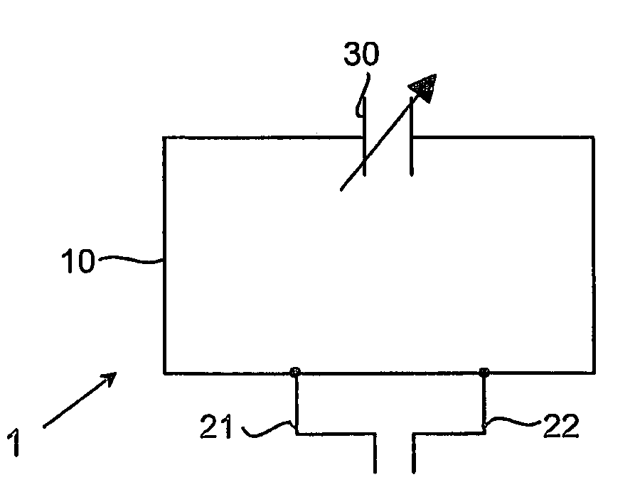
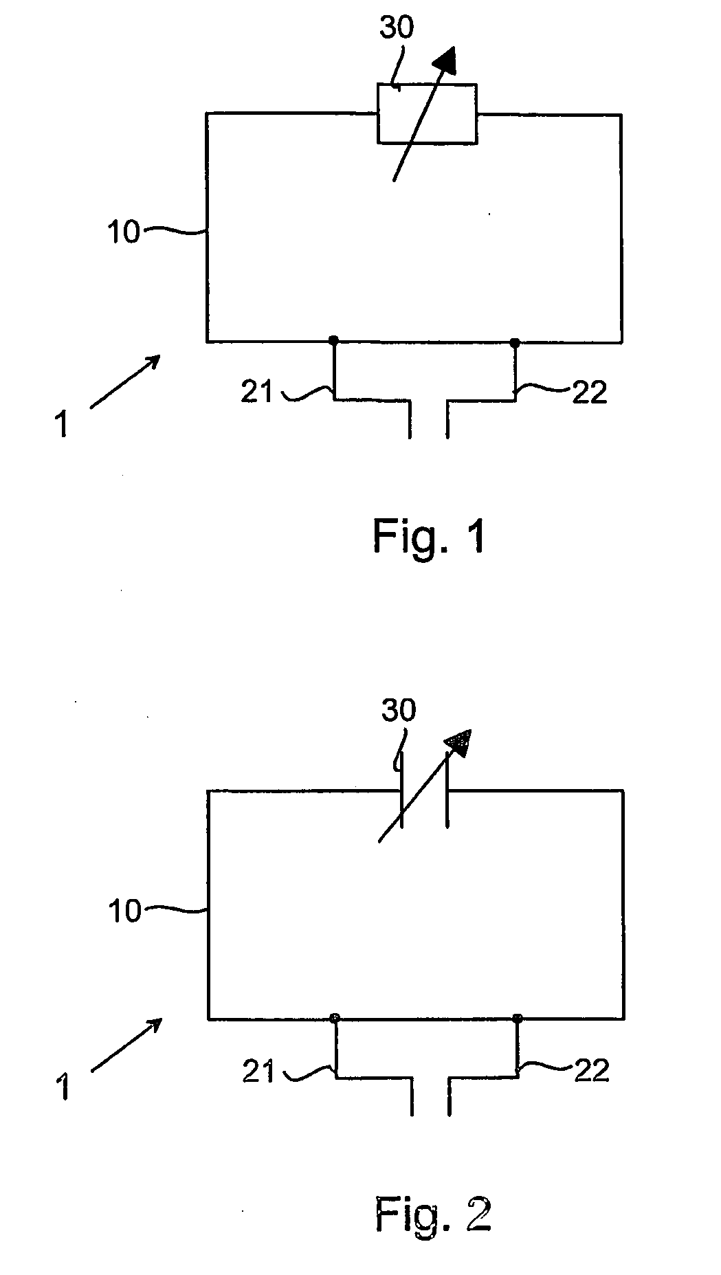
[0025]First with reference to FIG. 1, the general configuration of an antenna device according to the invention is shown, in this case a loop antenna. The antenna, generally designated 1, comprises a loop of thin electrically conductive wire. First and second feeding portions 21 and 22 are connected to the loop and are a...


PUM


Abstract

An antenna device for a portable radio communication device adapted for receiving radio signals comprises an internal radiating element (10) comprising at least one feeding portion (21, 22) connected to a receiver circuit (40). The radiating element (10) comprises an electrical impedance (30) that is controllable in dependence on the desired frequency range of the received signals, wherein the feeding portion (21, 22) is connected to a feeding input (40a, 40b) on the receiver circuit and the control input of the controllable electrical impedance (30) is connected to an output (40c) on the receiver circuit (40) intended for the control of the VCO resonance frequency of the receiver circuit. In that way an antenna device can be provided inside the casing of a small sized portable radio communication device, which has good performance throughout a narrow sub-band of a frequency band having a relatively low frequency, wherein the narrow sub-band can be adjusted in frequency so as to cover the entire frequency band, such as the FM radio band.

Description

FIELD OF INVENTION[0001]The present invention relates generally to antenna devices and more particularly to an antenna device for use in a radio communication device, such as a mobile phone, which is adapted for radio signals having a relatively low frequency, such as radio signals in the FM band.BACKGROUND[0002]Internal antennas have been used for some time in portable radio communication devices. There are a number of advantages connected with using internal antennas, of which can be mentioned that they are small and light, making them suitable for applications wherein size and weight are of importance, such as in mobile phones.[0003]However, the application of internal antennas in a mobile phone puts some constraints on the configuration of the antenna element. In particular, in a portable radio communication device the space for an internal antenna arrangement is limited. These constraints may make it difficult to find a configuration of the antenna that provides for a wide oper...

Claims


Application Information

Patent Timeline
Patent Type & Authority Applications(United States)
IPC IPC(8): H04B1/18H01Q1/24H01Q1/38H01Q5/00H01Q7/00
CPCH01Q1/243H01Q1/38H01Q7/005H01Q9/14H04B1/18H01Q1/24
Inventor KREBS, CHRISTEROLSSON, MAGNUSSTARCK, JONASKATSUNORI, ISHIMIYAVON ARBIN, AXEL
Owner LAIRD TECH AB (SE)
Why Eureka
Try Eureka