Controlling dead volume of a piston pump using an adjustment screw

Inactive Publication Date: 2008-11-20
MEDTRONIC INC
View PDF19 Cites 18 Cited by
  • Summary
  • Abstract
  • Description
  • Claims
  • Application Information

AI Technical Summary

Benefits of technology

[0006]The present invention includes an apparatus and method for reducing or eliminating ullage in a piston type pump. The apparatus includes an a

Problems solved by technology

This, in turn, causes the pressure in the piston chamber to fall.
Manufacturing tolerances in the production of the pump components may result in unwanted ullage (also known as “dead volume” or “dead space”) in the pumping chamber.
Ullage may include space that the pump does not physically displace during the forward stroke, resulting in an inaccurate pumped volume.
The dead space may lead to trapped a

Method used


Image

  • Controlling dead volume of a piston pump using an adjustment screw
  • Controlling dead volume of a piston pump using an adjustment screw
  • Controlling dead volume of a piston pump using an adjustment screw

Examples


Embodiment Construction

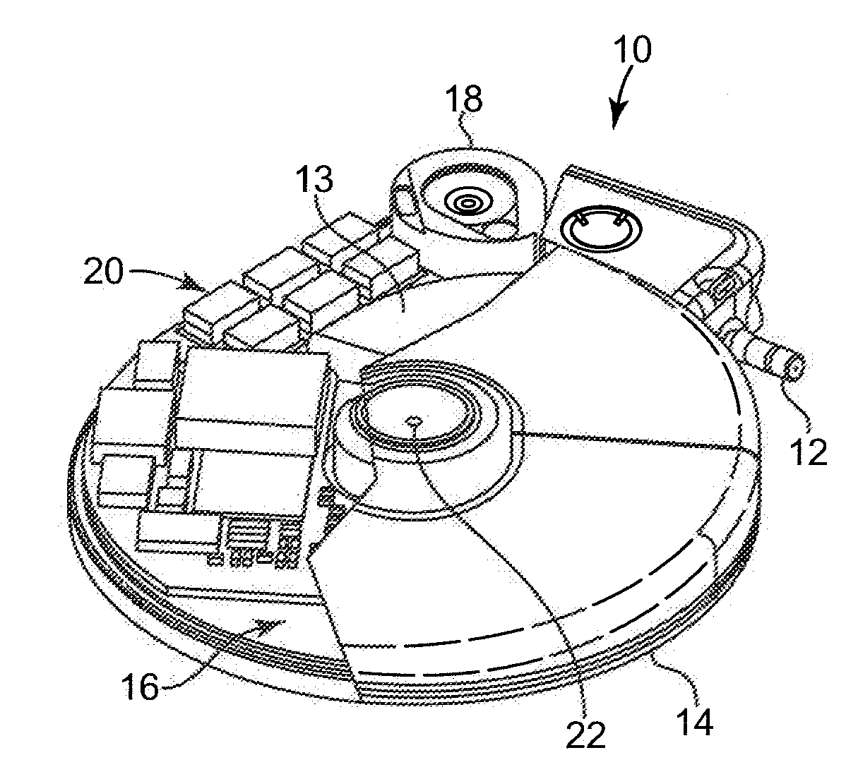
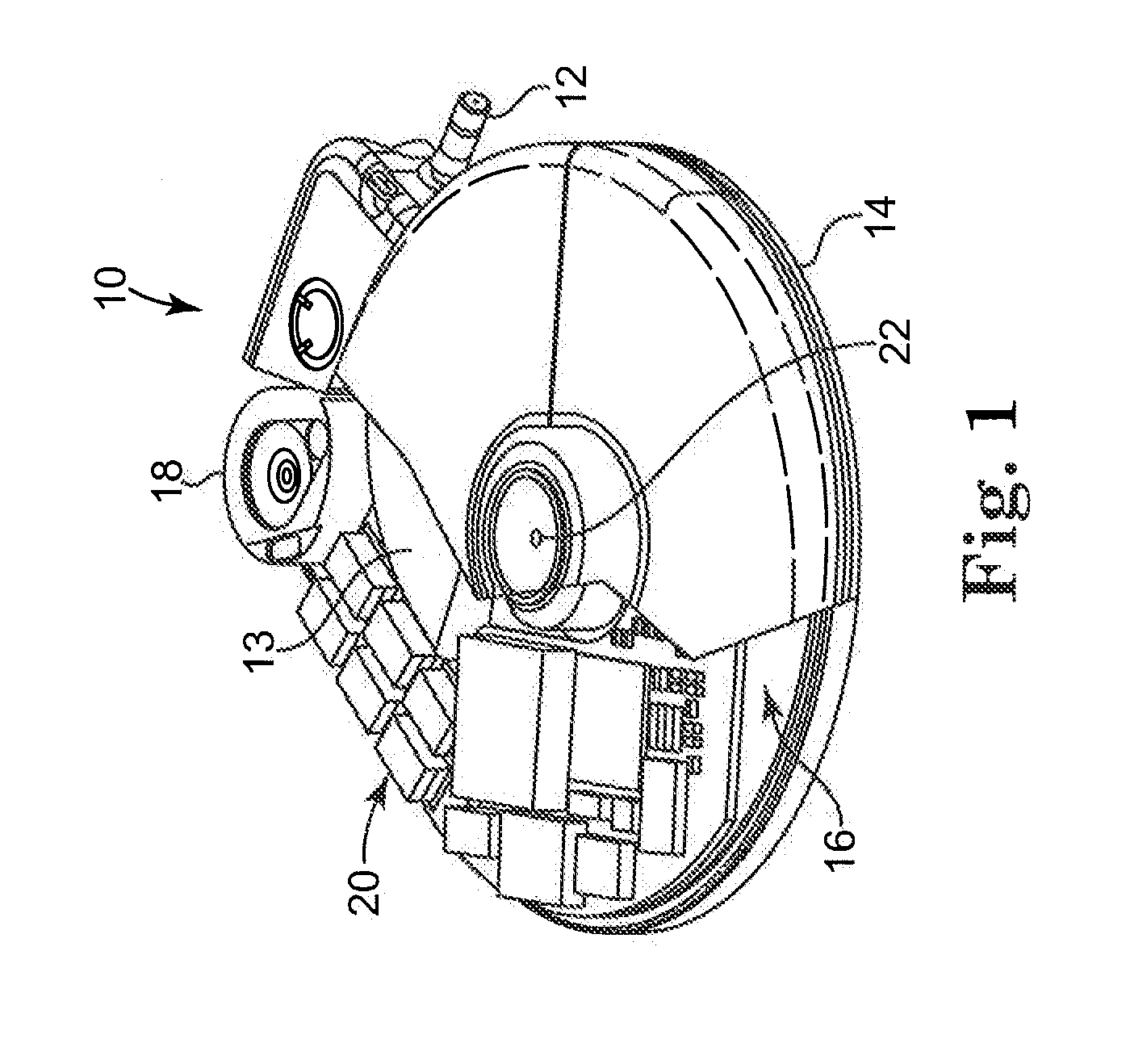
[0019]The present invention is an adjustment mechanism for selectively adjusting the forward position of an actuator member of a piston type pump in order to eliminate undesired dead space not pumped during the pumping stroke, also known as ullage. In particular, the adjustment mechanism is an adjustable stop member that can be positioned to contact a portion of the actuator member to halt the actuator in a desired position during a forward pumping stroke. Adjusting the position of the piston during the forward stroke of the actuator member allows for a user to eliminate any unwanted ullage, or dead space that may occur if the piston does not complete its stroke in the desired position.

[0020]The following detailed description is of the presently contemplated mode of implementing the invention. This description is not to be taken in a limiting sense, but is merely for the purpose of illustrating the general principles of embodiments of the invention. Furthermore, there is no intentio...


PUM

PropertyMeasurementUnit
Depthaaaaaaaaaa

Abstract

The present invention relates generally to infusion devices. More particularly, the present invention is directed toward an inexpensive design to adjust the dead space of a piston pump by adjusting the end position of the piston's forward stroke. The piston pump may include an actuator member with a piston that articulates between a retracted and a forward position in a piston channel. Movement between the retracted and forward position, a pumping stroke, may expel a known quantity of fluid. Because of manufacturing tolerances, the forward position may not exactly line up with the end of the piston channel, resulting in dead space, or ullage, that may result in less than desired accuracy for fluid volume pumped. Utilization of an adjustable stop or stop that contacts the actuator member at the desired forward position may allow for selective elimination of the ullage and precise adjustment of the fluid pumped.

Description

FIELD[0001]This invention relates generally to infusion devices. More particularly, the present invention is directed toward an adjustment mechanism to adjust the dead space of a piston pump by adjusting the end position of the piston's forward stroke.BACKGROUND[0002]Infusion devices may be used to deliver an infusion media (for example, a medication such as insulin) to a patient. Such devices may be implanted into a patient's body to deliver predetermined dosages of the infusion media to a particular location within the patient's body, for example, in the venous system, the spinal column, or within the peritoneal cavity.[0003]A known infusion device of the type described above includes a drive mechanism that includes a reciprocating pumping element made of a ferrous material. The reciprocating pumping element includes an actuator member with a piston portion that is coupled to an armature portion, also known as a piston actuator or pole. The piston portion is configured to reciproc...

Claims


Application Information

Patent Timeline
IPC IPC(8): A61M37/00
CPCA61M5/14216A61M5/14276Y10T29/49236F04B49/14F04B17/042
Inventor ELMOUELHI, AHMED
Owner MEDTRONIC INC
Why Eureka
Try Eureka