RF Ablation Catheter with Side-Eye Infrared Imager

a technology of infrared imager and catheter, which is applied in the field of endocardial rf catheter ablation, can solve the problems of contact stagnant blood, poor placement, stenosis of the pv,

Inactive Publication Date: 2008-11-20
OLYMPUS CORP
View PDF8 Cites 17 Cited by
  • Summary
  • Abstract
  • Description
  • Claims
  • Application Information

AI Technical Summary

Benefits of technology

[0011]In that position, the side-eye imager is directly viewing the target tissue site and the infrared images can be used to effect “a landing” of the electrode against the tissue while under continuous view of the real-time side-eye imager. In forward-viewing systems, the catheter tip needs to be pointed at the target tissue, followed by an articulation to aim the electrode side-on against tissue. The articulation prevents the possibility of viewing the electrode “landing” on tissue.
[0012]Imaging to the side is also advantageous in viewing lesions and in making a contiguous lesion. A forward-viewing catheter making a lesion on the electrode side needs to be rotated about 90 deg to view an ablation. The articulation and manipulation of this maneuver usually displaces the tip far away from the ablation site. In contrast, the side-eye imager is close enough to the electrode proximal end to view some of the lesion production. Sliding the catheter forward a few mm will place the lesion in full view of the side-eye imager and the electrode can be fine-positioned relative to this lesion to make a second connecting lesion contiguous with the first lesion, while maintaining the same articulation. Alternatively, the catheter can be dragged forward and as the catheter is dragged, lesion creation can be verified with the side-eye imager.

Problems solved by technology

Failure to do so may result in stenosis of the PV;(2) Tissue contact with a substantial part of the electrode portion against tissue.
PlacementIn anatomical ablations such as Aflutter or PV isolation, poor placement can lead tocomplications such as PV stenosis or incontiguous lesions and procedure failureContactLargest lesions produced with entire side of electrode contacting tissue.
If the proximal end is inpoor contact stagnant blood can be present at the very hottest point of the electrode(proximal end) and can lead to thrombi productionThrombiIn right heart, thrombi production can lead to electrode adhesion to the endocardial surfaceand removal can cause perforation.
In left heart, thrombi can cause strokes andmyocardial infarcts.
The interveningtissue between electrode and hottest tissue point usually perforates, leaving a crateredappearance in the lesions.. Steam pops can result in heart wall perforation.
All of these issues are difficult to evaluate with the current imaging technologies: fluoroscopy, intracardiac ultrasound (ICE) and navigational systems (e.g. CARTO™, EnSite™).
The navigational systems provide the most accurate tissue locater relative to cardiac structures and is the system of choice for complicated ablations such as pulmonary vein isolation, but like fluoroscopy does not address issues 2-5.

Method used


Image

  • RF Ablation Catheter with Side-Eye Infrared Imager
  • RF Ablation Catheter with Side-Eye Infrared Imager
  • RF Ablation Catheter with Side-Eye Infrared Imager

Examples


Embodiment Construction

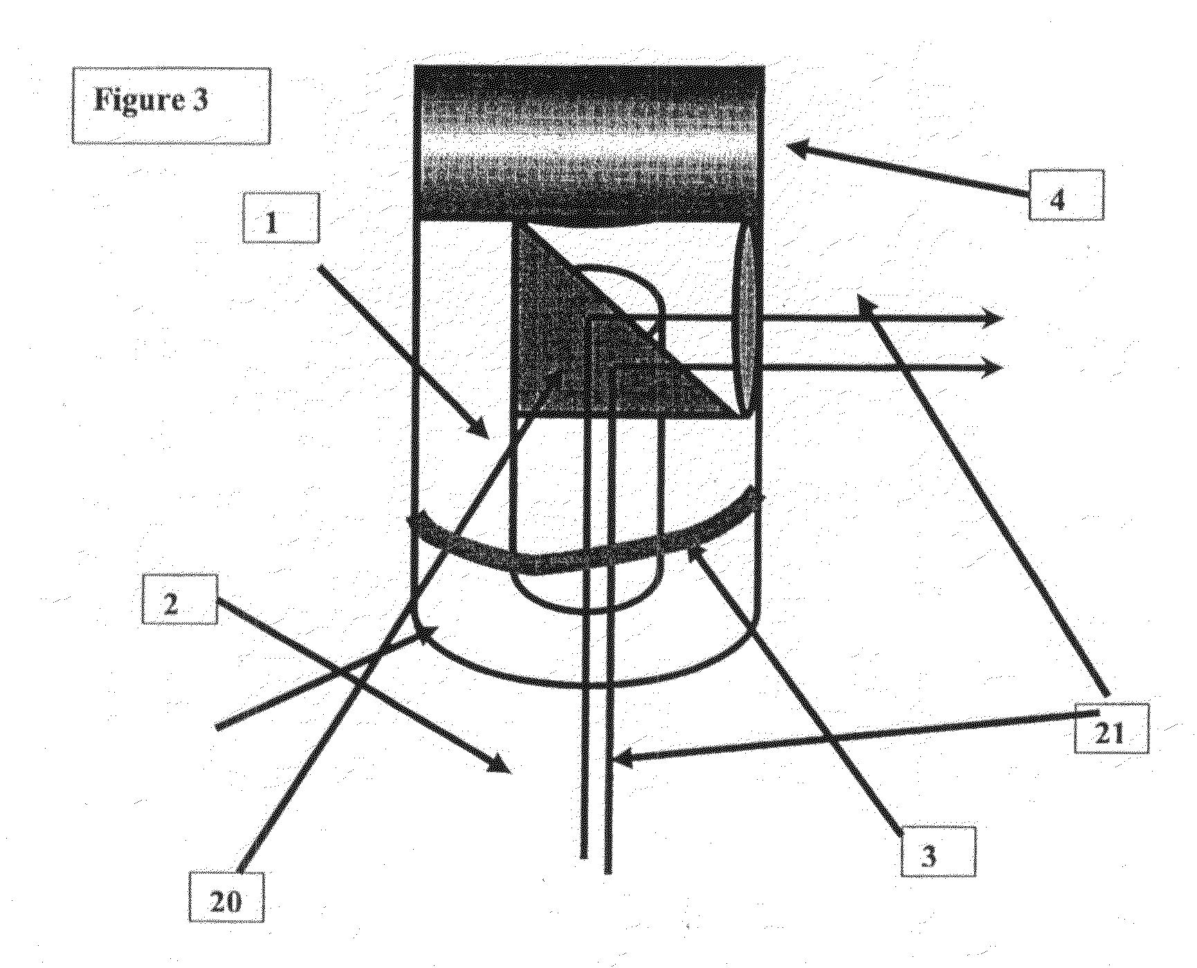
[0036]This device operates with the infrared imaging system as described in U.S. Pat. No. 6,178,346. As seen in FIG. 3, the imaging system has been modified through the use of a prism (20) which directs both illumination and returned reflected light in about a 90 deg angle to permit viewing on the side of the catheter.

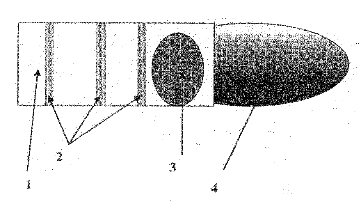
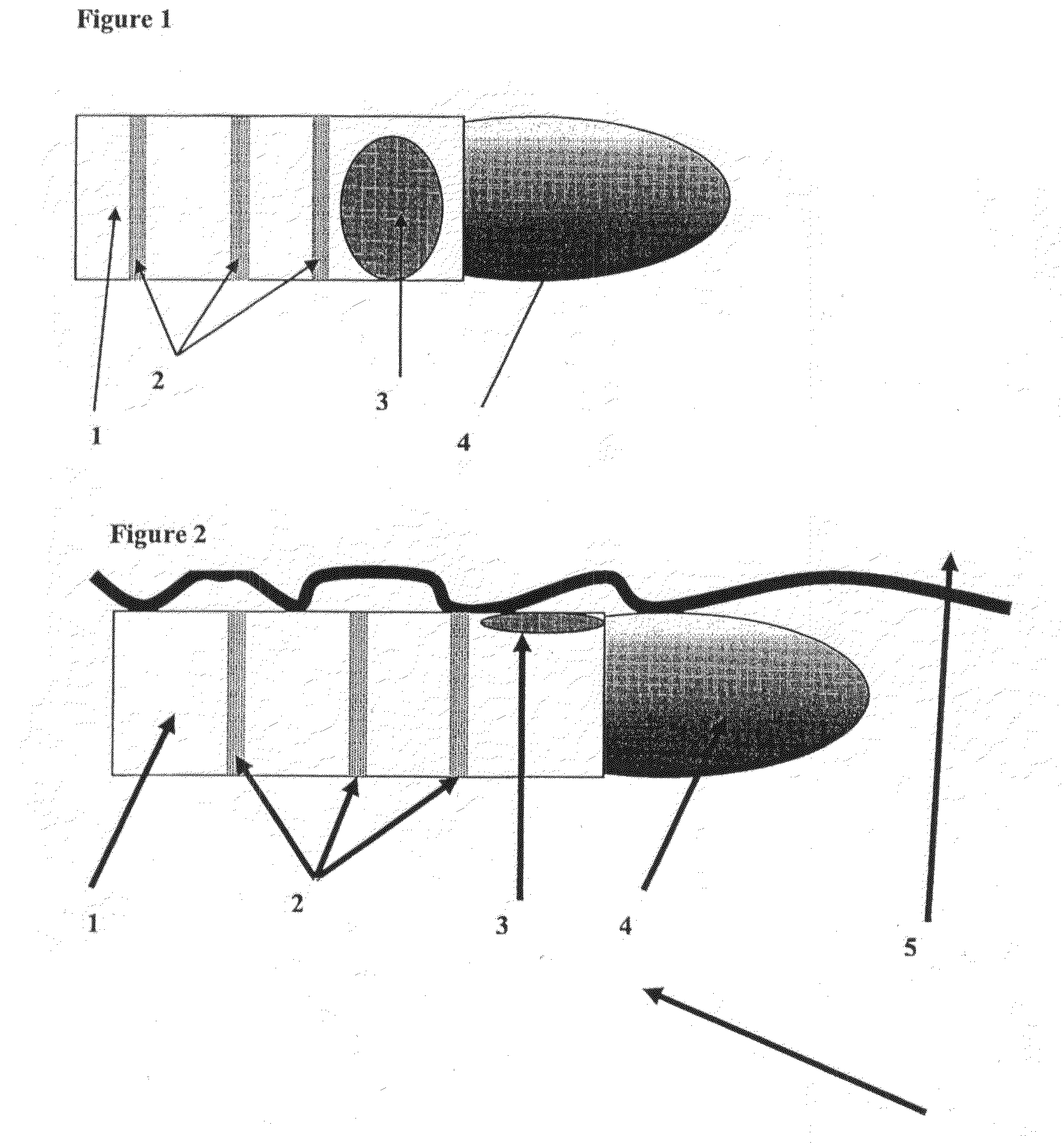
[0037]As seen in FIG. 1, the ablation catheter (1) contains three rings (2) to record electrograms of underlying tissue. Between the distal end of the electrode (4) and the first ring is located the side-eye imager (3). In FIG. 2, the catheter is rotated about 90 deg and placed against tissue (5).

[0038]As the side-eye imager is placed against tissue, the signal amplitude returning to the imaging bundle will dramatically increase. This will be seen on the infrared image as a high-detail image. Alternatively, the signal count could be used to construct a graphic, such as a bar which goes up to maximal level once the side-eye imager is seated on tissue. Since signal count...


PUM


Abstract

An ablation catheter has an imager useful in connection with an ablation operation such as used in the treatment of a cardiac arrhythmia. The catheter has an ablation electrode positioned on a catheter tip, and the imager is located on a side of the catheter. Because the catheter tip is generally articulated when the lesion is formed, this position of the imager provides an image that corresponds with the position of the catheter when it is used to form a lesion. Rings for recording tissue electrograms are also positioned on the catheter tip. This arrangement allows the user to accurately place and contact the electrode and to monitor the ablation process such as by viewing bubbles and thrombi that may undesirably be formed.

Description

BACKGROUND[0001]In the field of endocardial RF catheter ablation of cardiac arrhythmias, an electrode on the distal end of a catheter is placed on endocardial tissue and RF energy is applied to the tissue to ablate a critical piece of tissue responsible for maintaining the arrhythmia. Usually, the culprit tissue is only recognizable from its electrical potential characteristics. Sometimes, ablations are made using anatomical criteria for the ablation pattern. In atrial flutter or atrial fibrillation ablations, a contiguous line or circle is required to terminate the arrhythmia.[0002]The basic goal of RF ablation is to make a substantial lesion (100-600 cubic mm depending on electrode size and flow rate at the ablation site) and to avoid complications (thrombi, perforation, injuring heart structures or nearby non-heart structures). Critical to the success of the ablation are:[0003](1) For anatomical ablations such as atrial flutter or some pulmonary vein isolation procedures, placing...

Claims


Application Information

Patent Timeline
Patent Type & Authority Applications(United States)
IPC IPC(8): A61B18/14
CPCA61B18/1492A61B2018/00375A61B2018/00839A61B2019/5217A61B2019/5231A61B2090/3614A61B2090/373
Inventor AMUNDSON, DAVID C.
Owner OLYMPUS CORP
Why Eureka
Try Eureka