Receiving Apparatus and Receiving System

a technology which is applied in the field of receiving apparatus and receiving system, can solve the problems of not being applicable in any way to transmitters which fail to have the handleability of special control information, information is not always handled by all transmitters involved, and the technique taught by jp-, so as to avoid the dependency on type and reduce process complexity

Inactive Publication Date: 2008-11-20
HITACHI LTD
View PDF12 Cites 21 Cited by
  • Summary
  • Abstract
  • Description
  • Claims
  • Application Information

AI Technical Summary

Benefits of technology

[0009]According to this invention, it is possible to provide a receiver apparatus capable of obtaining and retaining the quality of received images by rea

Problems solved by technology

Unfortunately, the prior known technique as disclosed in JP-A-2005-210347 has difficulties which follow: an apparatus which performs control for obtaining and retaining the required level of quality must exchange a “special” kind of control information between the apparatus and its associated transmitter apparatus and then perform highly complicated processing tasks.
This information is not always handleab

Method used


Image

  • Receiving Apparatus and Receiving System
  • Receiving Apparatus and Receiving System
  • Receiving Apparatus and Receiving System

Examples


embodiment 1

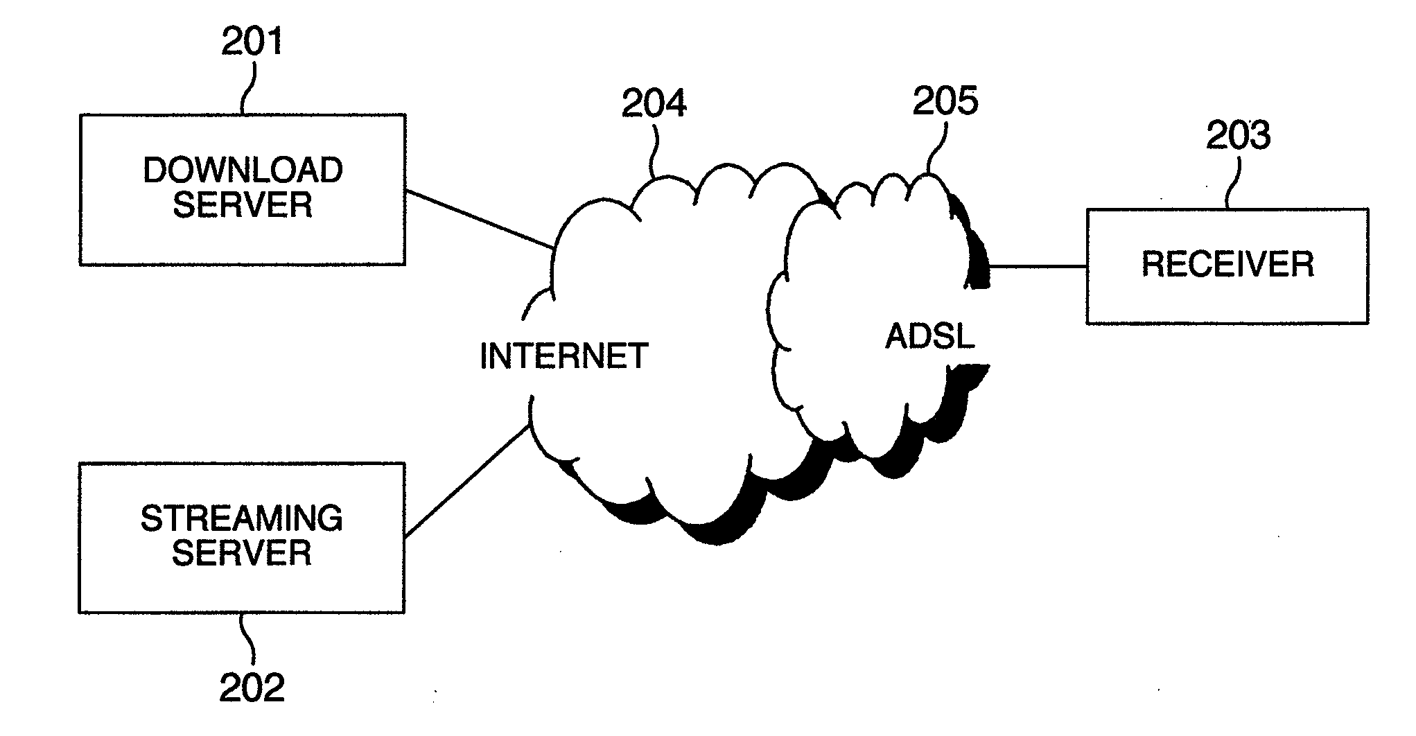
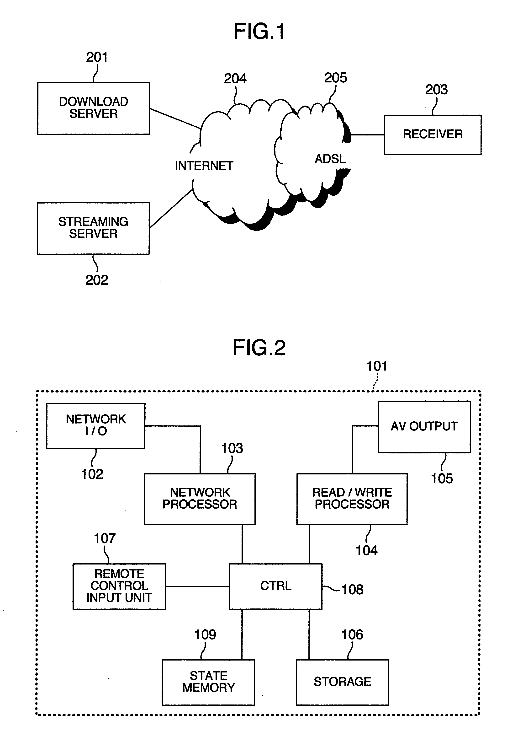
[0018]FIG. 1 is a diagram showing one example of the configuration of a network, to which a receiving apparatus 101 is connected. A download server 201 and a streaming server 202 are linked to Internet 204. The receiver 101 is linked to the Internet 204 via an access line, such as an asymmetric digital subscriber line (ADSL) 205 or the like.

[0019]When the receiver 101 issues a request for download start-up and sends it to the download server 201, the download server 201 transmits download data to the receiver 101. When this receiver 101 requests the streaming server 202 to start streaming, the streaming server 202 sends streaming data to the receiver.

[0020]Although in this embodiment an explanation will be given of a network environment made up of the Internet 204 and ADSL 205, the network configuration embodying the invention should not be limited only to this combination of the Internet and ADSL.

[0021]Another example of the access line is a fiber to the home (FTTH) line. A further...

embodiment 2

[0049]Next, an explanation will be given of a second embodiment of this invention with reference to FIG. 6. Regarding the same parts of this embodiment 2 as those of the above-stated embodiment 1, explanations thereof will be eliminated herein. Only its different parts will be described in detail below.

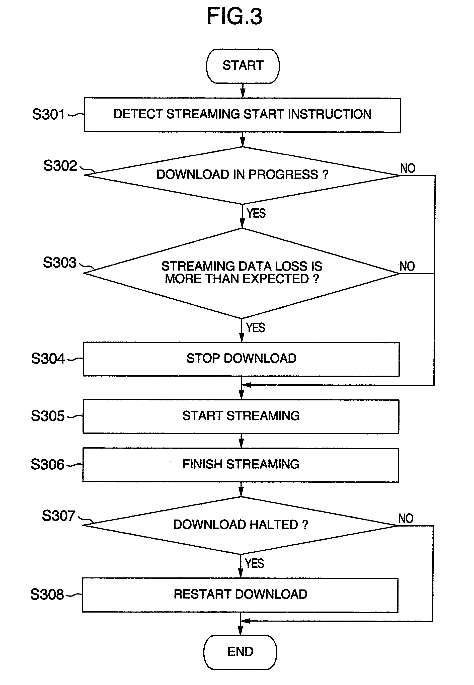
[0050]The control unit 108 is arranged in a manner which follows: during execution of download of contents, upon receipt of an instruction to start streaming, this control unit performs the processing for execution of download and streaming operations simultaneously while reducing the download speed of such contents to be downloaded.

[0051]One approach to lowering the download rate, which is employable in the case of transmission control protocols (TCP) being used for example, is to set a small value in a window size field of TCP header to thereby reduce the amount of data to be sent together at a time. Another employable approach is to set a small value in an option field of the TCP h...


PUM


Abstract

A receiver apparatus capable of retaining the quality of video images received through complexity-reduced small-load processing without having to depend upon its associated transmitter device. In cases where an instruction is made for receiving streaming data in the process of performing the processing of download data, when the loss of such streaming data is predicted to increase in such a way as to go beyond a predetermined degree if both the processing of download data and the processing of streaming data are performed at a time, the receiver performs the processing of the streaming data by giving thereto a higher level of priority.

Description

INCORPORATION BY REFERENCE[0001]The present application claims priority from Japanese application JP2007-127513 filed on May 14, 2007, the content of which is hereby incorporated by reference into this application.BACKGROUND OF THE INVENTION[0002]The present invention relates generally to a receiving apparatus and receiving system, and more particularly to a receiver device capable of securing the quality of images received.[0003]In recent years, video delivery services via networks are becoming widespread. The currently available video delivery techniques include a streaming method and a download method, wherein the former is for reproducing on a real-time basis the contents data to be delivered from a transmitter apparatus while a receiver apparatus is in the process of receiving the data at the same time whereas the latter is for temporarily storing or “saving” the received contents data in the receiver and for performing playback after having acquired an entirety of such content...

Claims


Application Information

Patent Timeline
IPC IPC(8): G06F15/16G06F13/00H04N7/173H04N21/438H04N21/44H04N21/4425
CPCH04L47/10H04L47/2416H04L47/2433H04L47/2475H04L47/25H04N7/17318H04N21/4334H04N21/44209H04N21/4424H04N21/4583H04N21/472H04N21/475H04N21/4882H04N21/64322
Inventor TOYOMURA, TAKASHIMORI, NAOKI
Owner HITACHI LTD
Why Eureka
Try Eureka