Single web grid with reinforced bulb

a technology of reinforced bulb and web grid, applied in the direction of load-supporting pillars, walls, other domestic objects, etc., can solve the problems of uncertain costs, and achieve the effects of reducing production costs, increasing strength, and high beam strength

Inactive Publication Date: 2008-11-27
USG INTERIORS INC
View PDF24 Cites 6 Cited by
  • Summary
  • Abstract
  • Description
  • Claims
  • Application Information

AI Technical Summary

Benefits of technology

[0006]The invention approaches an ideal construction because it locates the material added for increased strength into the area of the bulb. This is advantageous since the additional material is situated as far or nearly as far as possible from the neutral axis, located near the mid-height of the web, thereby obtaining a high beam strength.
[0007]Where the double layer extends along less than the full perimeter of the reinforcing bulb, it can be arranged, more or less, on either side of the plane of the web relative to a flange construction that is half double layer and essentially half single layer. The invention, by utilizing the same gauge of material, for different duty ratings, enables the manufacturer to reduce its costs of production. The invention permits the manufacturer to keep the material content as low as practical and at the same time allows certain labor costs and machine down time to be avoided. Labor costs and machine down time are minimized since there is no need to change over the rolling dies to run different gauges of strip stock.
[0008]The invention can extend the versatility of existing tooling since it can allow manufacture of higher duty products, even though such tooling is limited to running lighter gauge material. Down time or change over time to run higher or lower duty product in a roll forming machine is virtually eliminated with the invention since the only change essentially required is that of changing the width of the stock being fed to the machine. Economy can also be gained with the invention since the material used for different load ratings need only vary in width. This enables the grid runner manufacturer to buy and inventory master coils of one gauge and to simply slit such roll stock to the widths needed. The disclosed grid can be easier to install and, therefore, has greater marketability because it is easier to field cut the web by hand with a tin snips, for example, than to cut grid tee made with heavier stock.

Problems solved by technology

The common practice of producing different rated grid tees by changing the thickness of the stock used to make the tees has certain costs associated with the labor and manufacturing down time necessary for changing over and adjusting the roller dies that are used for different gauges of sheet stock.

Method used


Image

  • Single web grid with reinforced bulb
  • Single web grid with reinforced bulb
  • Single web grid with reinforced bulb

Examples


Embodiment Construction

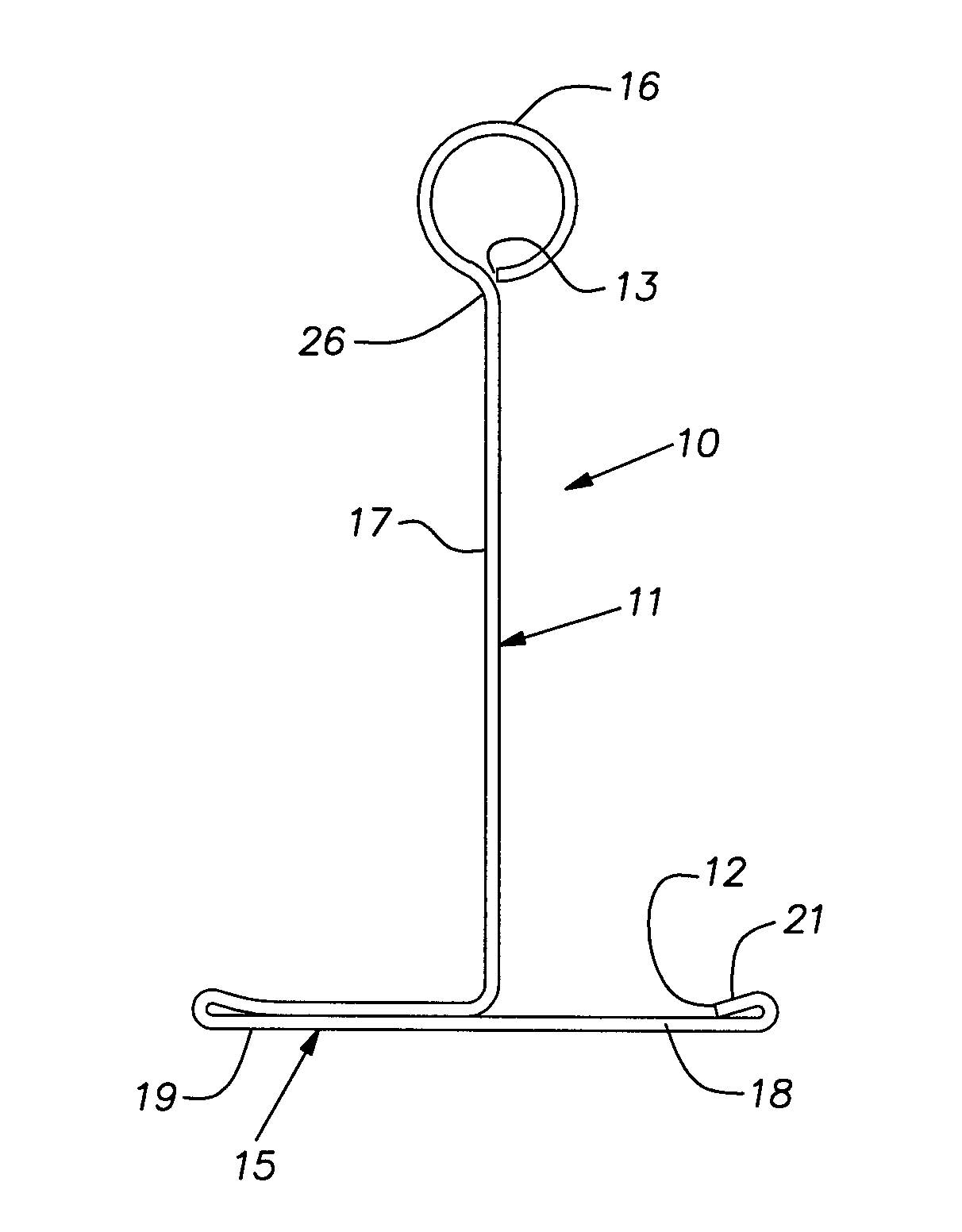
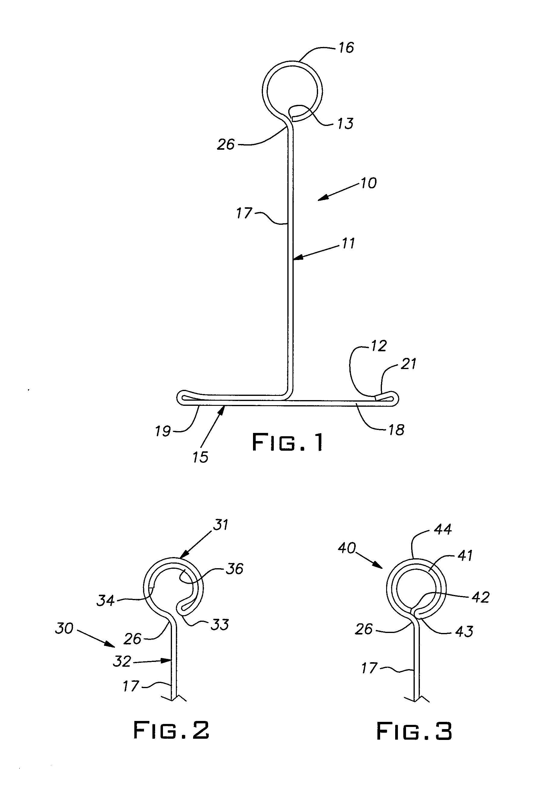
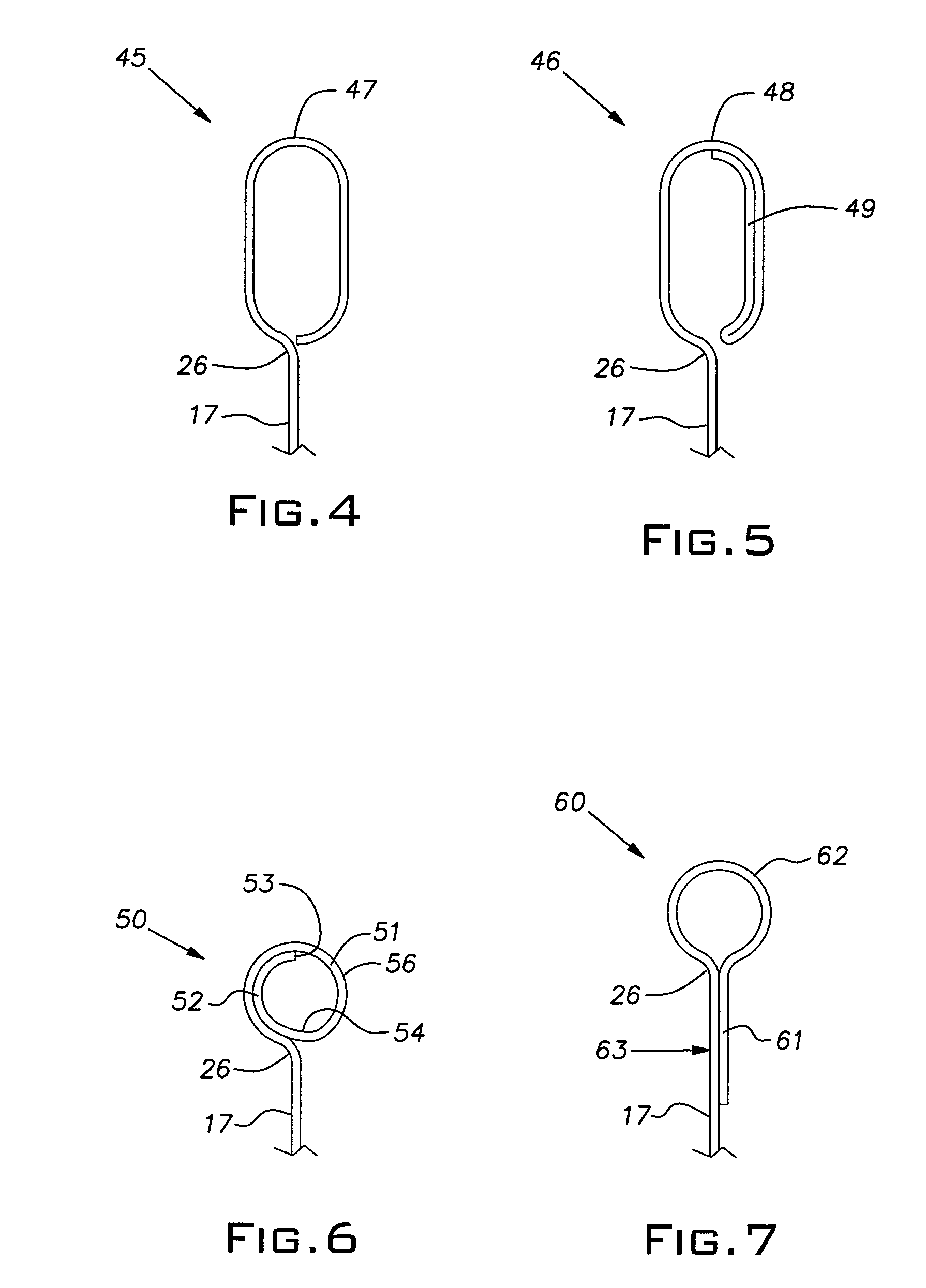
[0016]The invention pertains to a method of producing sheet metal grid runners of the inverted tee style. The grid runner tees are used in construction of suspended ceilings, soffits, and like structures. FIG. 1 shows a conventional prior art grid runner tee 10 in cross-section. The grid tee or runner 10 is roll-formed from a sheet metal strip 11, such as 0.021 / 0.024″ gauge galvanized steel, for example. It will be understood that other gauges and other metals such as aluminum can be used in practicing the invention. The tee 10 is shaped from a flat strip in a conventional roll forming machine in which rolls, sometimes referred to as dies or tooling, at successive stages or stations along the rolling direction progressively form the strip into the desired form. Material adjacent opposite edges 12, 13 of the strip 11 in this tee shape as well as those described below, can be shaped concurrently as the strip 11 progresses through the roll forming machine. The tee 10 as well as other t...


PUM

PropertyMeasurementUnit
lengthsaaaaaaaaaa
lengthsaaaaaaaaaa
lengthsaaaaaaaaaa

Abstract

Manufacture of roll formed one piece sheet metal grid tees that affords different load ratings with the same gauge and quality of sheet stock and the same overall cross-section dimensions by varying the width of the strip used to make the tees and disposing material added for increased load rating at the area of the hollow reinforcing bulb of the tees.

Description

[0001]The invention relates to grid tees for suspended ceilings and, in particular, to an improved grid tee construction and method of its production.PRIOR ART[0002]Suspended ceilings typically use a rectangular metal grid made up of main runners and cross runners. The grid supports ceiling panels or tiles normally laid onto the upper faces of runner or tee flanges or, less commonly, large panels are screwed to lower faces of the flanges. The runners commonly have an inverted T-shaped cross-section and are typically roll-formed from strips of sheet metal. The lower flange portions of the tee section extend horizontally from both sides of a vertical central web. The upper edge of the web is conventionally reinforced with a hollow bulb.[0003]The grid runners or tees are supplied in different strengths, e.g. intermediate and heavy duty, to satisfy the requirements of a particular installation. The specified strength or rating can depend, for example, on the use of a space below the cei...

Claims


Application Information

Patent Timeline
Patent Type & Authority Applications(United States)
IPC IPC(8): E04B9/18
CPCE04B9/067B21D5/08Y10T29/49625B21D47/01Y10T29/49627B21D19/12
Inventor LALONDE, PAUL D.
Owner USG INTERIORS INC
Why Eureka
Try Eureka