
Cyclone dust-separating unit for use in vacuum cleaner

a technology of dust-separating unit and vacuum cleaner, which is applied in the direction of filtration separation, separation process, vortex flow apparatus, etc., can solve the problems of reducing the lifespan reducing the dust-separating efficiency of the vacuum cleaner, and deteriorating suction force of the suction motor, etc., and achieves simple structure and improved dust-separating efficiency.

Inactive Publication Date: 2008-11-27
SAMSUNG GWANGJU ELECTRONICS CO LTD
View PDF9 Cites 32 Cited by
  • Summary
  • Abstract
  • Description
  • Claims
  • Application Information

AI Technical Summary

Benefits of technology

[0009]An aspect of the present disclosure is to address at least the above problems and / or disadvantages and to provide at least the advantages described below. Accordingly, an aspect of the present disclosure is to provide a cyclone dust-separating unit for use in a vacuum cleaner capable of improving a dust-separating efficiency and more surely preventing dust or dirt from being re-scattered while having a relatively simple structure.
[0010]Another aspect of the present disclosure is to provide a cyclone dust-separating unit for use in a vacuum cleaner capable of easily separating a whirling current generating unit and a dust collecting bin, thereby allowing the cyclone dust-separating unit to easily fabricate, maintain and repair, as well as to easily dump dust or dirt collected therein.

Problems solved by technology

However, in the conventional vacuum cleaner, if the dust or dirt is somewhat accumulated in the dust bag or the filter of the dust collecting unit after the cleaning operations are repeatedly carried out, the suction force of the suction motor is deteriorated and thus a dust-separating efficiency of the vacuum cleaner is lowered.
Particularly, if the dust bag is filled with the dust or dirt or the filter is choked with the dust or dirt, the suction motor may be overloaded, so that a lifespan thereof is reduced.
Accordingly, a user should frequently carry out troublesome operations that she or he separates the dust bag or the dust bin and the filter from the cleaner body and then replaces the dust bag with a new one or cleans the dust bin and the filter.
Accordingly, each of the cyclone dust-separating units are disadvantageous in that a dust-collecting efficiency is low, a re-scattering of the dust or dirt is severe, and a construction is so complicated that it is inconvenient to dump the collected dust or dirt from the dust collecting bin.

Method used


Image

  • Cyclone dust-separating unit for use in vacuum cleaner
  • Cyclone dust-separating unit for use in vacuum cleaner
  • Cyclone dust-separating unit for use in vacuum cleaner

Examples


Embodiment Construction

[0028]Hereinafter, a cyclone dust-separating unit for use in a vacuum cleaner according to exemplary embodiments of the present disclosure will be described in detail with reference to the accompanying drawing figures.

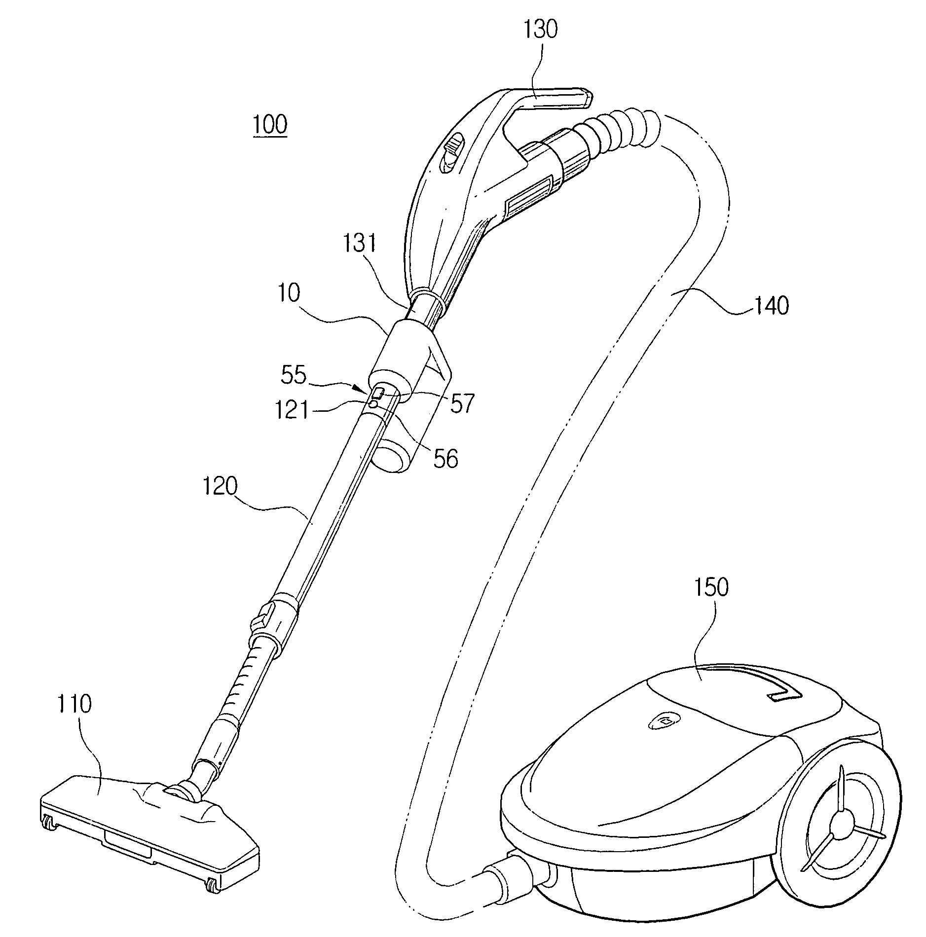
[0029]FIG. 3 is a view exemplifying an example of a vacuum cleaner 100 to which a cyclone dust-separating unit 10 according to an exemplary embodiment of the present disclosure is applied.

[0030]Referring to FIG. 3, the vacuum cleaner 100 includes a suction nozzle 110 to draw in air laden with dust or dirt, a telescopic extended tube 120 connected to the suction nozzle 110, an operating handle 130, a cyclone dust-separating unit 10 disposed between the operating handle 130 and the extended tube 120, a suction hose 140 connected to the operating handle 130, and a cleaner body 150 connected to the suction hose 140 and divided into a dust-separating chamber (not illustrated) and a motor chamber (not illustrated).

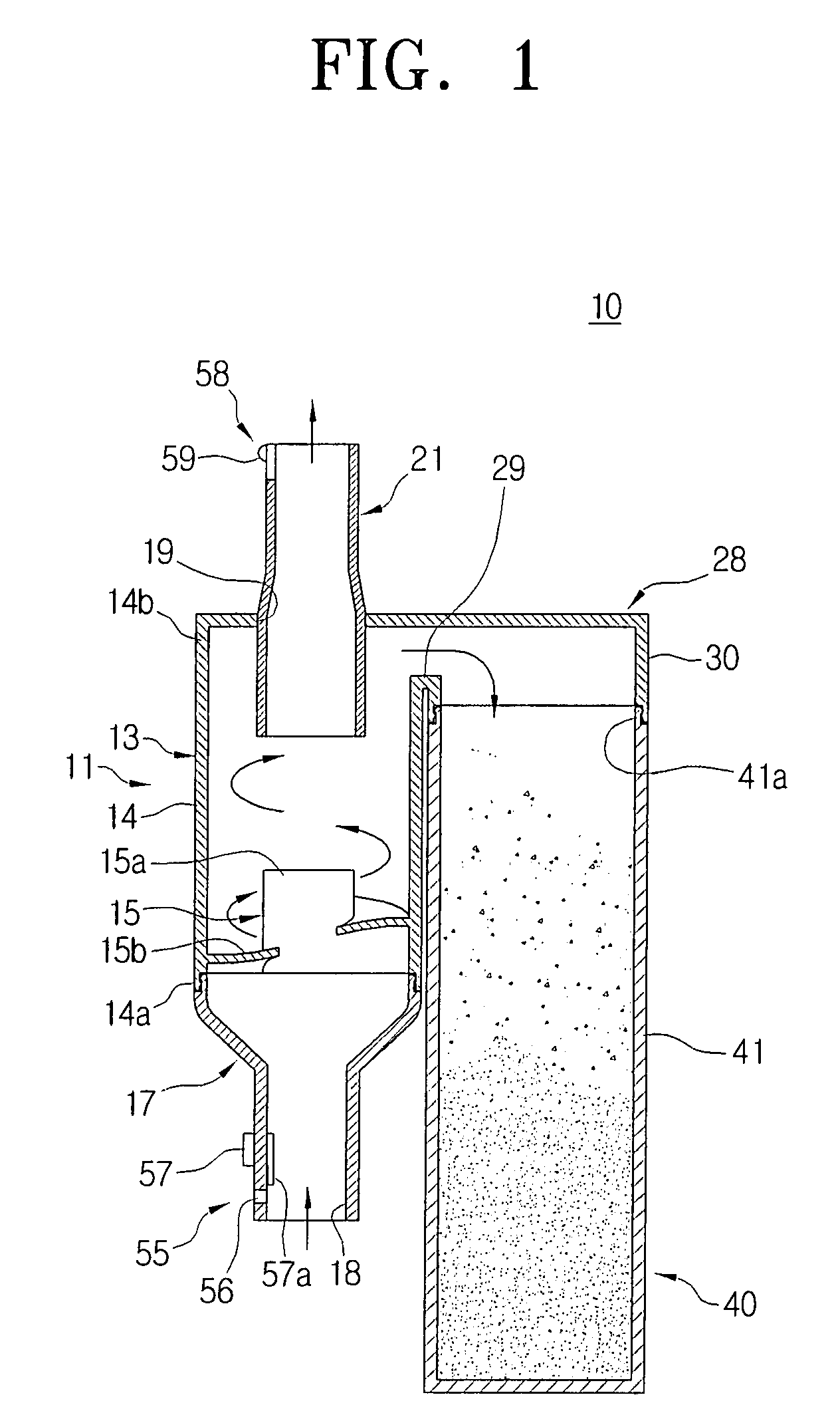
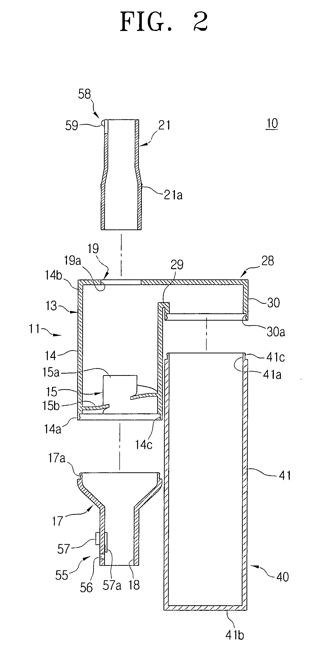
[0031]FIGS. 1 and 2 are an assembled cross-sectional view and...


PUM

PropertyMeasurementUnit
Lengthaaaaaaaaaa
Transparencyaaaaaaaaaa

Abstract

A cyclone dust-separating unit is provided that includes a whirling current generating unit to rotate air drawn in through a suction nozzle, and a dust collecting bin having opened and closed ends to collect and store dust separated by a whirling current. The generating unit and the bin are separate tube members, and the generating unit includes a cyclone body having a first end with an air inlet and a second end with an air outlet, a spiral guide member on the first end to guide air flowed in through the air inlet in a spiral shape, an outflow pipe on the second end to extend to the outside of the cyclone body while penetrating through the air outlet, and a dust guide to connect a dust discharging opening with the opened end and to guide dust or dirt discharged through the dust discharging opening, to the opened end.

Description

CROSS-REFERENCE TO RELATED APPLICATIONS[0001]This application claims the benefit under 35 U.S.C. § 119(a) of Korean Patent Application No. 10-2007-0049343, filed on May 21, 2007, in the Korean Intellectual Property Office, the entire contents of which are hereby incorporated by reference.BACKGROUND OF THE INVENTION[0002]1. Field of the Invention[0003]The present disclosure relates to a vacuum cleaner. More particularly, the present disclosure relates to a cyclone dust-separating unit for use in a vacuum cleaner, which separates and collects dust or dirt from air drawn in through a suction nozzle in cleaning.[0004]2. Description of the Related Art[0005]In general, a vacuum cleaner generates a strong suction force by using a suction motor, and thus draws in dust or dirt adhered to a surface to be cleaned to clean the surface to be cleaned. Such a vacuum cleaner is usually provided with a dust collecting unit having a dust bag or a cyclone, a dust bin and a filter to separate and colle...

Claims


Application Information

Patent Timeline
IPC IPC(8): A47L9/16B01D45/12B04C5/185
CPCA47L9/1608A47L9/1683A47L9/248B01D45/16B04C3/00B04C3/06B04C2003/003A47L9/02A47L9/104A47L9/165A47L9/1658A47L9/1691A47L9/10A47L9/16
Inventor HAN, JUNG-GUYNOH, JANG-KEUNIL-DU, JUNG
Owner SAMSUNG GWANGJU ELECTRONICS CO LTD
Learn More