[0009]The invention is based on the idea that the individual pitch devices are designed such that they can identify disturbance situations autonomously and then, in the event of a disturbance, move the rotor blades to the shut-down position, without this being dependent on an appropriate
signal from the central control device. The individual pitch devices can also autonomously identify a disturbance situation and can react appropriately, that is to say can move the respective rotor blade associated with them to the safe shut-down position. In this case, the movement of the rotor blades is monitored both in the event of a disturbance and during normal operation so that any discrepancies which may occur from the nominal state can be monitored and compensated for directly. For this purpose, the movement of the rotor blades is individually appropriately matched to the respective conditions which may result in each case from the
wind speed, turbulence, incident-flow direction or operating state of the wind energy installation, or of the other individual pitch devices. The invention therefore makes it possible to achieve an optimum rotor blade adjustment behavior, in particular while slowing down, that is to say while the rotor blades are being moved to the shut-down position.
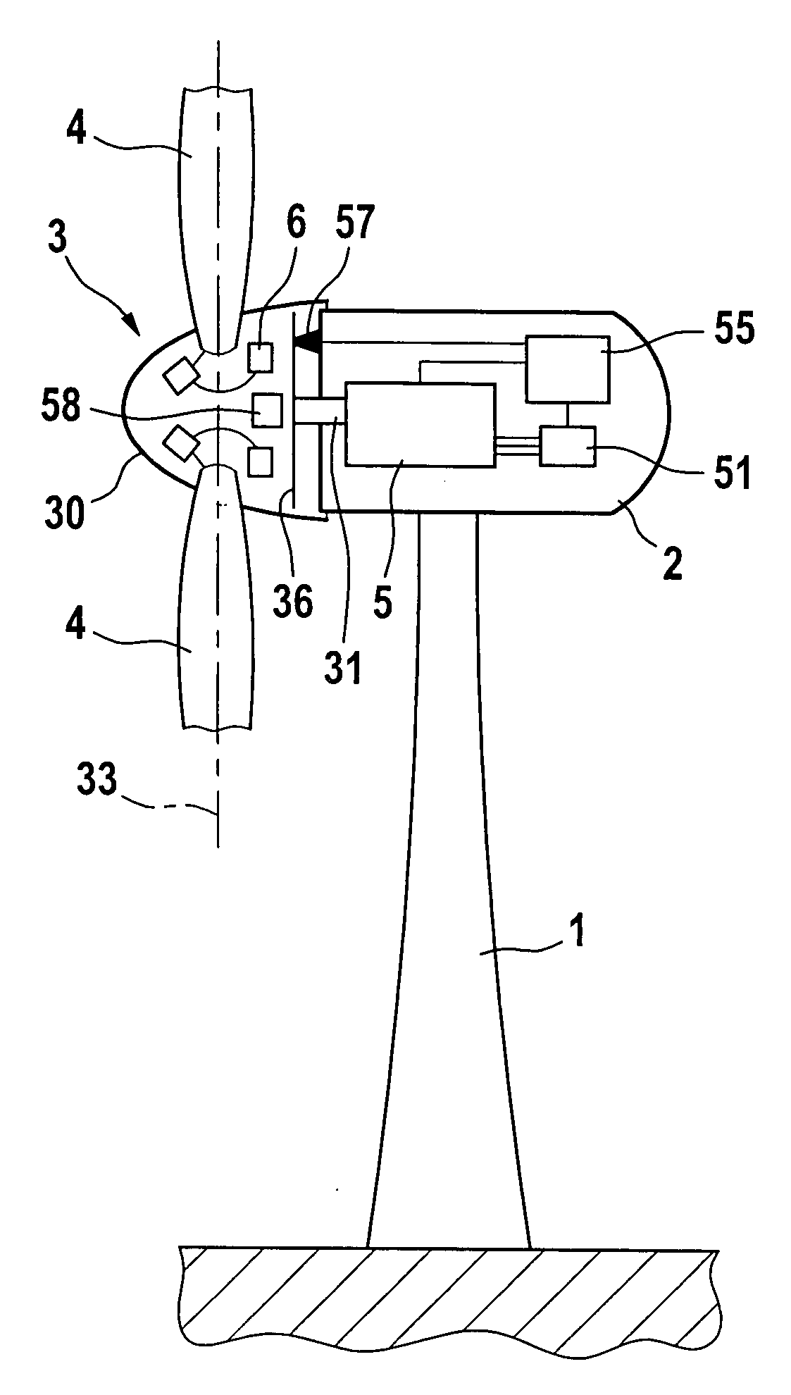
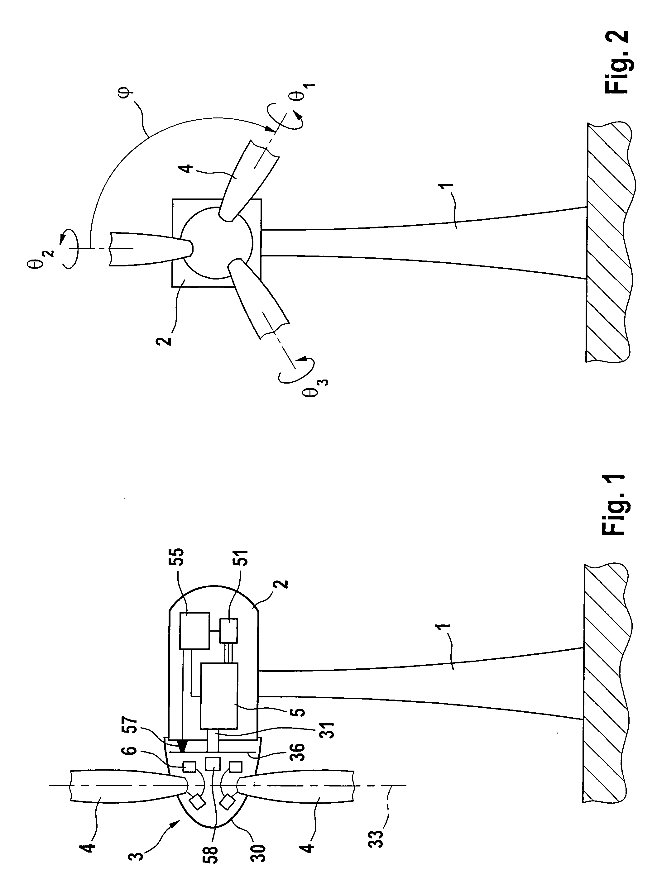
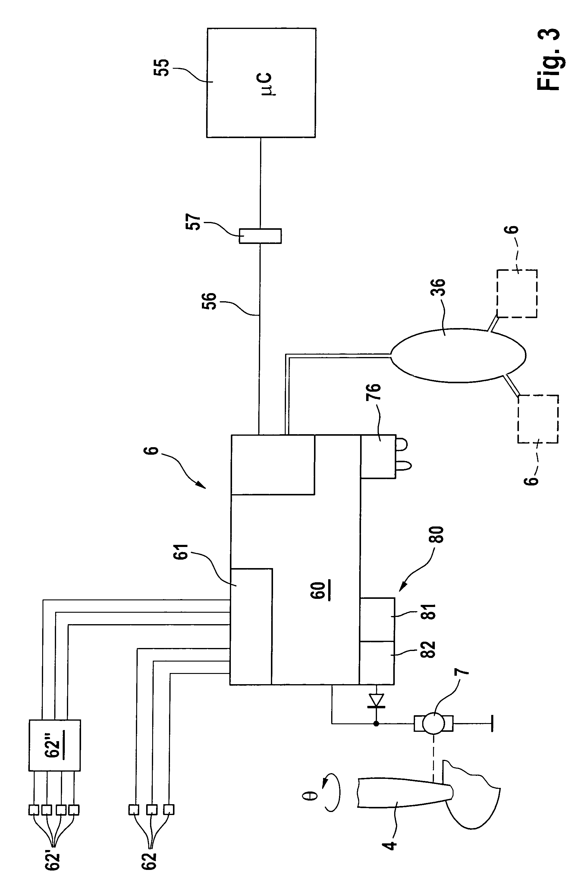
[0022]The invention also relates to a wind energy installation having a generator for production of electrical energy, a rotor which drives the generator and has variable pitch rotor blades and a central control device, with individual pitch devices being provided for the rotor blades and comprising an adjustment drive, with the rotor blades being adjustable in order to slow down the wind energy installation to a shut-down position, and with the individual pitch devices being part of a hub
monitoring system which is fixed to the rotor and comprises a measurement sensor and a
communication link to the central control device, in which case the invention provides for the hub
monitoring system which is fixed to the rotor to also have a disturbance situation
detector which is designed to identify abnormal operating states, and is connected to a
tripping device which adjusts the rotor blades to a shut-down position. This variant differs from that explained above essentially in that, during normal operation, the functions of the rotor are not monitored locally by the individual pitch devices but centrally, either by the central controller or by a central hub
monitoring system. According to this variant of the invention, the hub monitoring
system has the disturbance situation
detector. The disturbance situation is identified by the hub monitoring
system, and the individual pitch devices are operated as necessary. There is no need for the individual pitch devices to have their own regulators, and they may be omitted. In addition, disturbance situation detectors may be provided on the individual pitch devices, although this is not necessary. This variant of the invention is distinguished in that it provides a monitoring functionality in the hub with the disturbance situation detector, which monitoring functionality is independent of the central control device and of the communication link to it. Slowing down is therefore also ensured when the central control device and / or the communication link to it are / is faulty. The complexity required for this is minimal and, in the simplest case, it is sufficient for the hub monitoring
system to have a common disturbance situation detector for the individual pitch devices. The hub monitoring system may be restricted to one core task, specifically to monitor disturbance situations. This allows the hub monitoring system to be of simple design, with corresponding advantages for
operational safety. This variant of the invention is therefore particularly suitable as a final safety facility, in order to ensure that the wind energy installation will invariably be slowed down in a controlled manner.

