
Flyback Converter

a converter and flyback technology, applied in the direction of electric variable regulation, process and machine control, instruments, etc., can solve the problem of still quite high dissipation, and achieve the effect of low dissipation

Inactive Publication Date: 2008-11-27
BOBINADOS DE TRANSFORMADORES
View PDF14 Cites 9 Cited by
  • Summary
  • Abstract
  • Description
  • Claims
  • Application Information

AI Technical Summary

Benefits of technology

[0004]It is therefore an object of the present invention to provide a converter of the above mentioned type with lower dissipation.
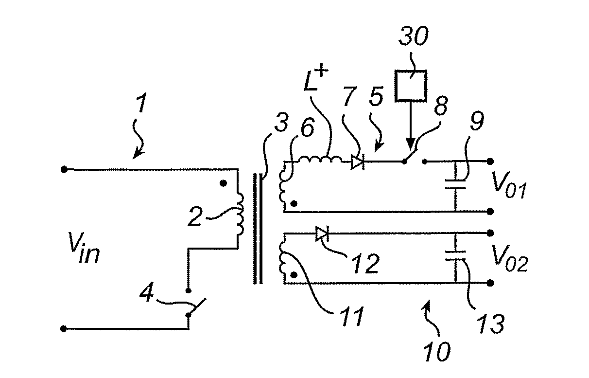
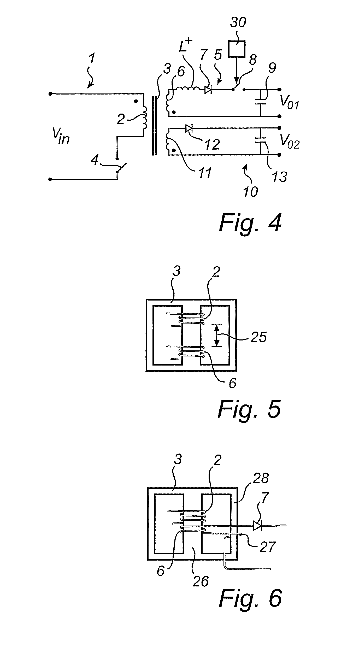
[0007]By increasing the inductance, the RMS current and hence the dissipation can be kept lower. This is because the increased inductance limits the rate of the rise of the current in the first secondary winding. The increased inductance alters the current distribution in such a way, that the peak current in the first secondary winding is limited. Since the peak current is lowered, the secondary control keeps the switch conducting for a longer period of time as to control the output voltage. Therefore, the resulting current waveform has a significantly lower RMS value. Moreover, second commutations, where the first and second output circuit begin their flyback strokes at different instants can be avoided to a great extent. Thus the increase of the inductance is particularly advantageous in cases where otherwise second commutations could occur.
[0012]In a preferred embodiment, the converter may further comprise control means for variably controlling the output of the first secondary output circuit. Together with the increased inductance, the control means allows the provision of a variable voltage within a certain range, without the risk of introducing a second commutation interval in the circuit.

Problems solved by technology

One problem associated with the converter of the above mentioned type is that, even if the dissipation in the secondary output circuit is considerably lower than if a linear control circuit were used, the dissipation is still quite high.

Method used


Image

  • Flyback Converter
  • Flyback Converter
  • Flyback Converter

Examples


Embodiment Construction

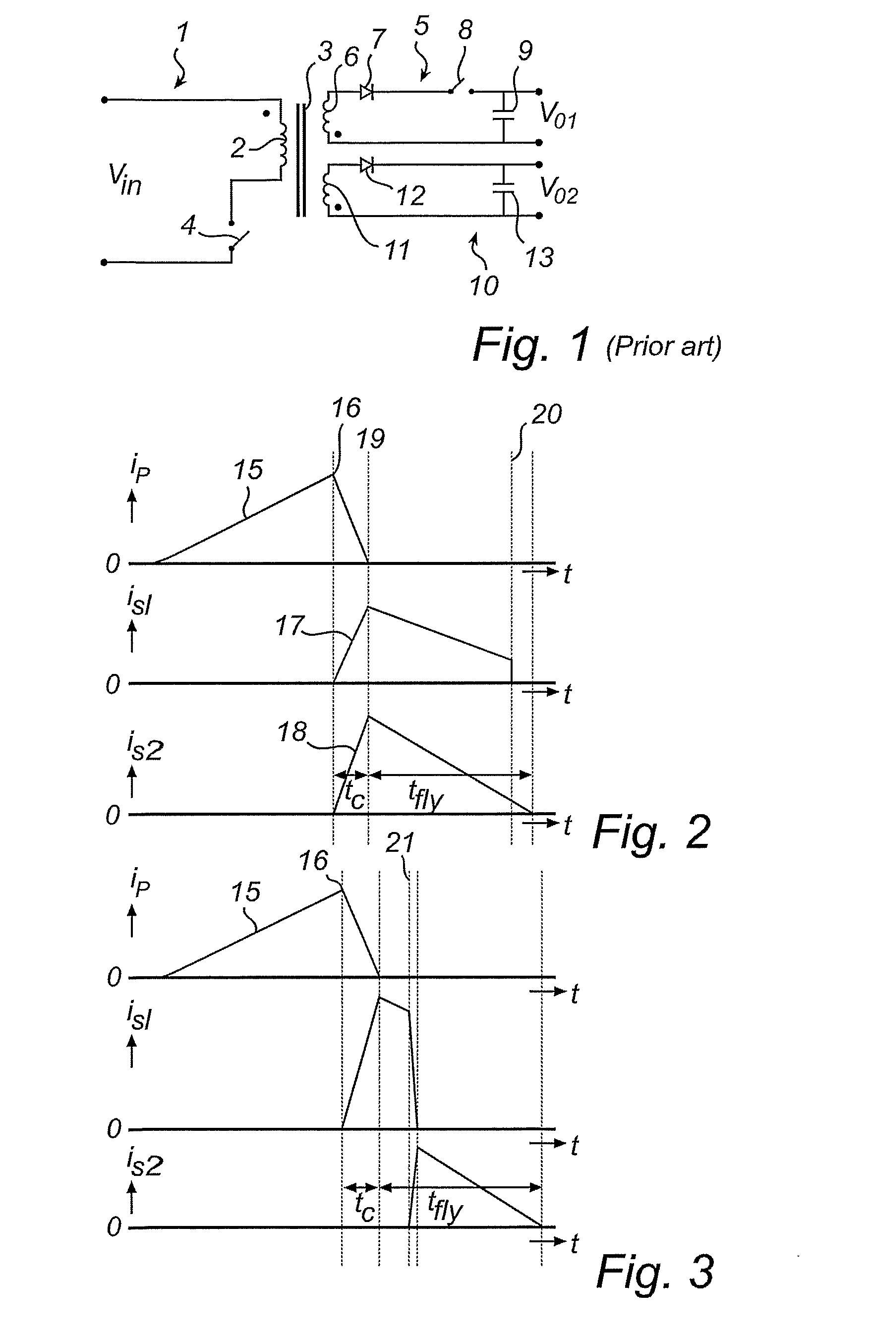
[0025]FIG. 1 illustrates schematically a flyback converter with switched secondary side control according to the prior art. A flyback converter provides galvanic insulation between the input side and the output side, and can simultaneously deliver multiple different output voltages at its secondary side. Flyback converters may be found in numerous consumer electronics products, such as television sets, DVD players and -recorders, satellite receivers, etc.

[0026]As described in EP 0772284 A2 one output circuit may be provided with a switched secondary side regulator, which allows one output voltage to be precisely regulated to a predetermined desired value, without the use of a high dissipation linear regulator.

[0027]Such a flyback converter comprises a primary side input circuit 1, comprising a primary winding 2 wound on a transformer 3 and a primary switch element 4, such as a MOSFET, in series with the primary winding 2. The input circuit 1 receives an input voltage Vin. The switch...


PUM


Abstract

The present invention relates to a multiple output flyback converter having a switch regulated output circuit (5). To avoid a second communication interval, due an output voltage in this secondary controlled output that is lower what is implied by its number of winding turns, the inductance of this circuit is increased. This can preferably be done by increasing the leakage inductance of the winding (6) in the regulated circuit.

Description

FIELD OF THE INVENTION[0001]The present invention relates to a flyback converter, comprising a primary side input circuit, having a primary winding wound on a transformer and a primary switch element in series with the primary winding, a first output circuit, having a first secondary winding, wound on the transformer and connected in series with a rectifying element and a secondary switch element, and at least a second output circuit, having a second secondary winding, wound on the transformer and connected in series with a rectifying element.BACKGROUND OF THE INVENTION[0002]A DC / DC converter of the above mentioned type is disclosed e.g. in EP, 0772284 A2. Such a device, having a switched secondary control arrangement, allows the output of the first secondary output circuit to be accurately regulated to a desired value, without the use of a high dissipation linear control circuit.[0003]One problem associated with the converter of the above mentioned type is that, even if the dissipa...

Claims


Application Information

Patent Timeline
IPC IPC(8): H02M3/335
CPCH02M3/33561H02M3/28H02M3/325
Inventor JULICHER, PAUL JOHANNES MARIESMIDT, PIETER JAN MARKRIBARI, FATMIRVAN HORCK, FRANCISCUS BERNARDUS MARIE
Owner BOBINADOS DE TRANSFORMADORES
Learn More