Bobbin, coil-wound bobbin, and method of producing coil-wound bobbin

a technology of bobbins and bobbins, which is applied in the direction of transformers/inductance coils/windings/connections, magnets, etc., can solve the problems of low coil lamination factor, insufficient torque, and inability to achieve adequate magnetomotive force, so as to achieve the effect of maintaining or even enhancing torque performance and improving lamination factor of coils

Inactive Publication Date: 2008-11-27
MINEBEA CO LTD
View PDF5 Cites 28 Cited by
  • Summary
  • Abstract
  • Description
  • Claims
  • Application Information

AI Technical Summary

Benefits of technology

[0020]The present invention has been made in light of the above problems, and it is an object of the present invention to provide a bobbin which allows an increase in the number of coil turns while absorbing variation in a wire diameter and variation in a bobbin dimension to thereby successfully achieve alignment winding in multiple layers, and also to provide a method for forming a coil of multilayer alignment on the bobbin described above thus producing a coil-wound bobbin.
[0030]According to the present invention, there is provided a bobbin which allows an increase in the number of turns of a coil wound on the bobbin in multilayer alignment while the variation of the wire diameter and the bobbin dimension is absorbed. Consequently, the lamination factor of the coil can be improved, and if the bobbin described above is used in a stepping motor, the torque performance can be maintained or even enhanced in the effort of downsizing.

Problems solved by technology

In the alignment winding, however, there is a problem that a winding becomes loose due to variation in wire diameter or bobbin dimension, which lowers the lamination factor of a coil thus failing to achieve an adequate magnetomotive force.
Accordingly, the winding space of the small stepping motor is inevitably limited thus failing to generate an adequate magnetomotive force, which results in failure to achieve a sufficient torque.
Further, the coil does not have flanges or like members thus allowing its both end faces to be substantially exposed, and therefore may possibly be loosened, deformed or damaged at the time of assembly process and the like.

Method used


Image

  • Bobbin, coil-wound bobbin, and method of producing coil-wound bobbin
  • Bobbin, coil-wound bobbin, and method of producing coil-wound bobbin
  • Bobbin, coil-wound bobbin, and method of producing coil-wound bobbin

Examples


first embodiment

[0047]the present invention will be described with reference to FIGS. 5 and 6.

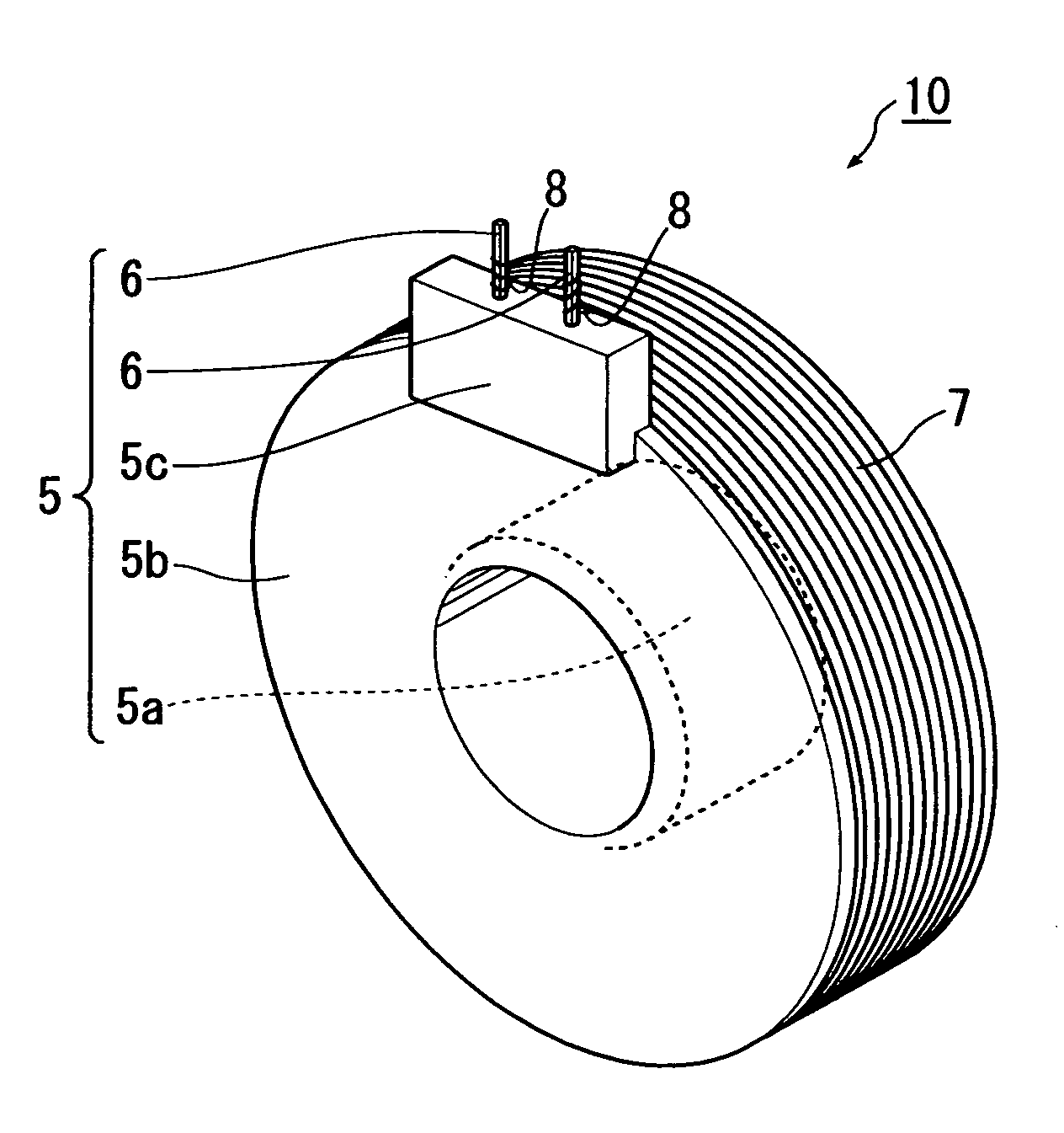
[0048]Referring to FIG. 5, a bobbin 5 according to the first embodiment is made of a non-magnetic synthetic resin (for example, liquid crystal polymer) by resin molding and integrally includes a spool portion 5a, a flange 5b disposed at one end of the spool portion 5a, and a terminal pin block 5c having a plurality (two in the figure) of terminal pins 6. Thus, no flange is provided at the other end of the spool portion 5a. Also shown in FIG. 5 is a coil 7 which is formed such that a wire 8 is wound around the spool portion 5a of the bobbin 5, thus a coil-wound bobbin 10 is structured.

[0049]Referring to FIG. 6, a wire winding machine (not shown) includes a spindle 1 which includes an outer portion 2 having a hollow and an inner portion 3 inserted in the hollow of the outer portion 2. The wire winding machine further includes a wire holder.

[0050]The bobbin 5 is put on the inner portion 3 of the spindle 1 and...


PUM

PropertyMeasurementUnit
diameteraaaaaaaaaa
electrical angleaaaaaaaaaa
shapeaaaaaaaaaa

Abstract

A bobbin includes a spool portion having a hollow circular cylinder shape and adapted to have a wire wound thereon in multilayer alignment; a flange integrally disposed at one end of the spool portion; and a terminal block integrally disposed at the flange and adapted to terminate the wire, wherein a formula: D×N−D / 2□L<D×N+D / 2 is established where L is the effective length of the spool portion, D is the diameter of the wire, and N is the number of turns of the wire for the first layer of the multilayer alignment.

Description

CROSS-REFERENCE TO RELATED APPLICATIONS[0001]This application claims priority to Japanese Patent Application No. 2007-136366, filed May 23, 2007, which is expressly incorporated herein by reference and made a part hereof.FEDERALLY SPONSORED RESEARCH OR DEVELOPMENT[0002]Not Applicable.TECHNICAL FIELD[0003]The present invention relates to a bobbin and a coil-wound bobbin, especially for use in a small stepping motor, and further to a method of producing a coil-wound bobbin having a wire wound in multilayer alignment.BACKGROUND OF THE INVENTION[0004]In order to increase the lamination factor of a coil, alignment winding is conventionally performed in which a wire is wound in multiple layers with adjacent wires set in tight contact with each other. In the alignment winding, however, there is a problem that a winding becomes loose due to variation in wire diameter or bobbin dimension, which lowers the lamination factor of a coil thus failing to achieve an adequate magnetomotive force.[00...

Claims


Application Information

Patent Timeline
Patent Type & Authority Applications(United States)
IPC IPC(8): H01F27/29H01F7/06
CPCH01F5/02H01F41/0633Y10T29/49071H01F41/0687H01F41/0666H01F41/076H01F41/082H01F41/098
Inventor SUZUKI, YUZURUTAKAHASHI, YUUKI
Owner MINEBEA CO LTD
Why Eureka
Try Eureka