[0010]It is an object of the multifunction smoke alarm unit to also contain an
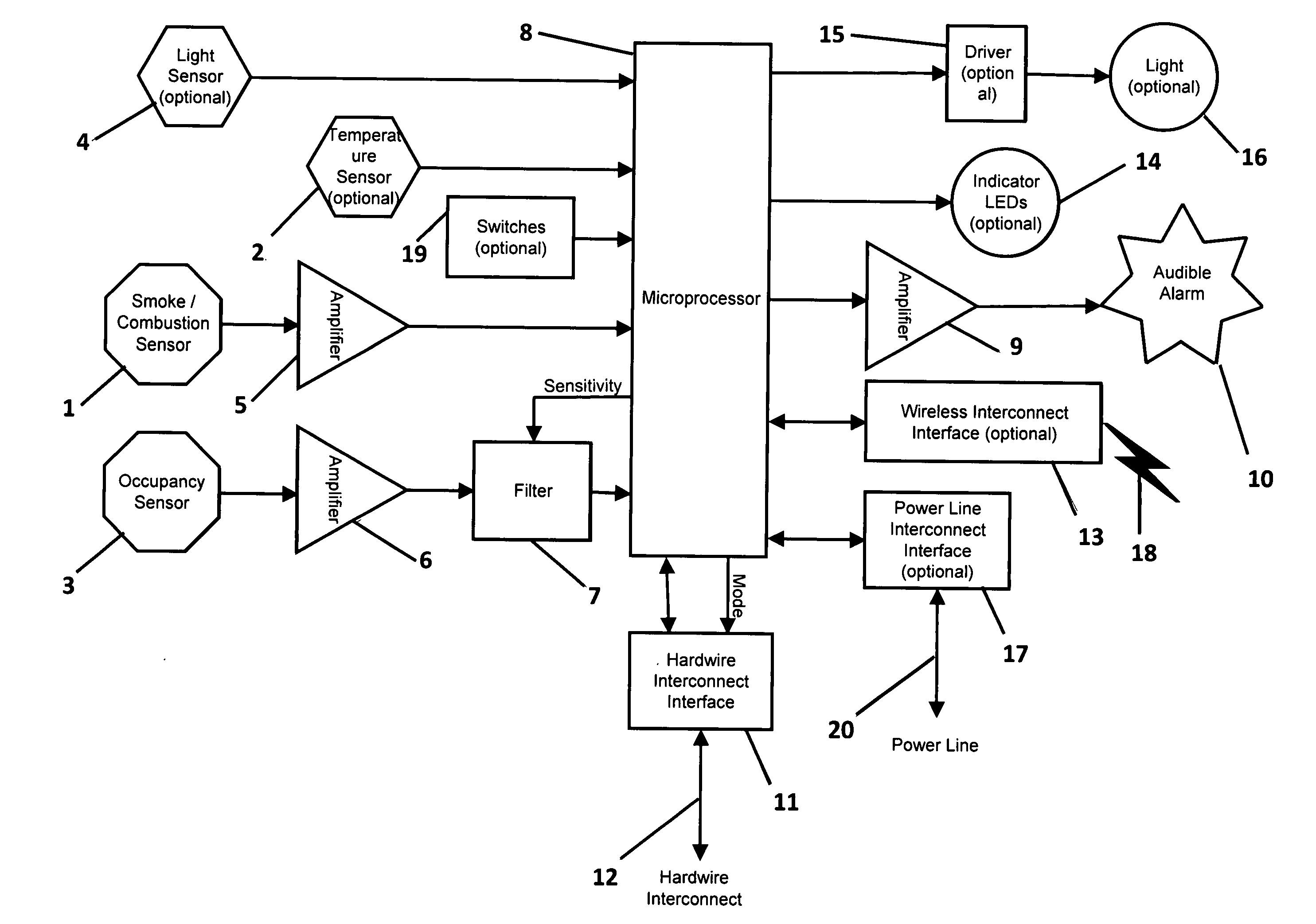
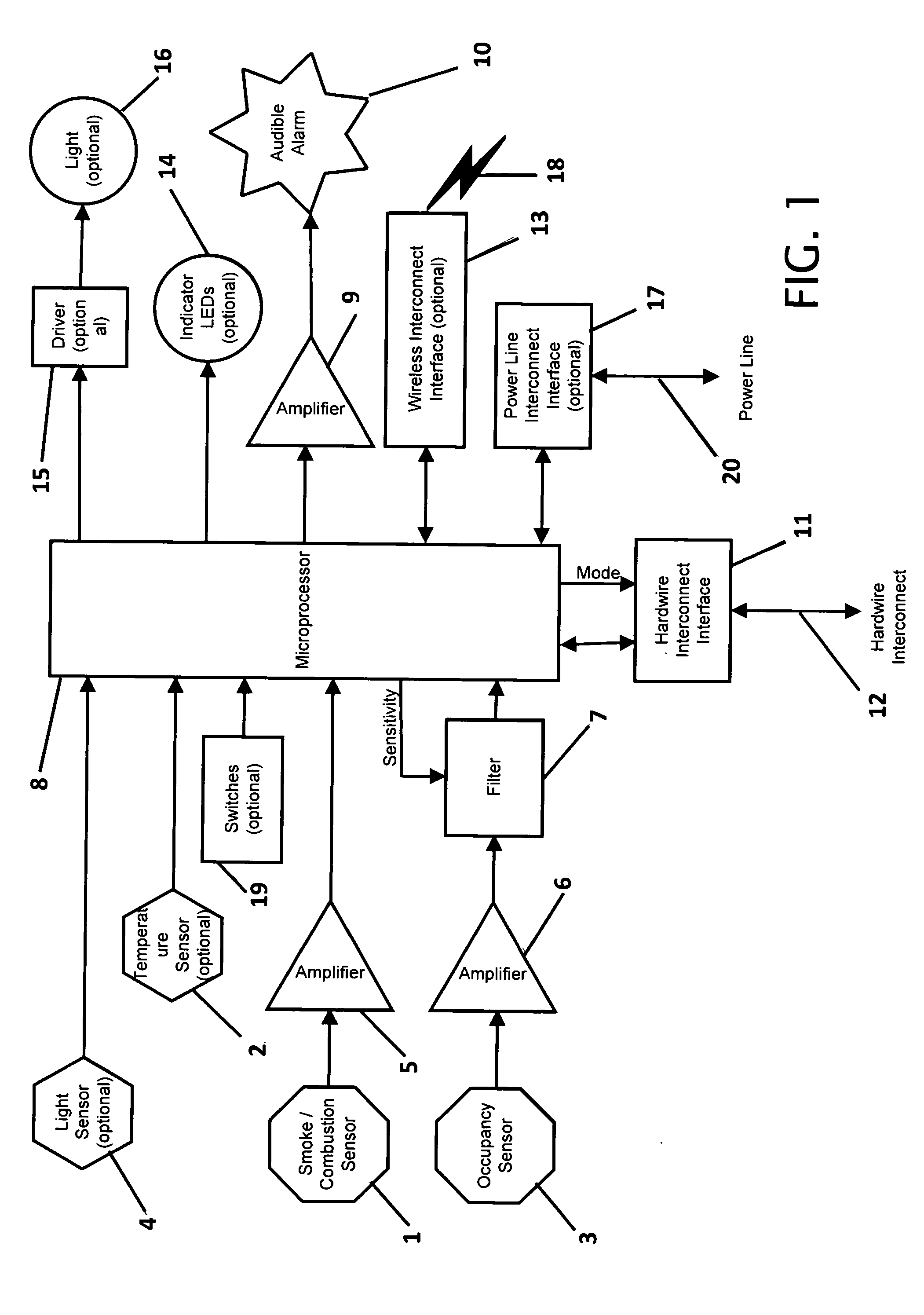
occupancy sensor component, for detecting the presence or absence of occupants. The occupancy sensor is integrated with the other smoke alarm components, such that greater utilization of all components is achieved. The occupancy sensor is used for multiple purposes, including intrusion warning, visitor annunciation, vacancy determination, control of the light component, control of an external HVAC
system, control of external lights, control of ceiling fans, and / or control of other external systems, by way of the interconnect component. The occupancy sensor can operate in various sensitivity
modes in order to best perform its
current function such as normal sensitivity, for occupancy detection, high sensitivity, for vacancy detection and low sensitivity, for minimizing false intruder alarms. The occupancy sensor provides a wide detection area for occupants within the building. The lights,
ceiling fan, etc., in an area or room can be prevented from being turned off unnecessarily, and an energy-saving HVAC system will not enter the setback mode unnecessarily. It provides a means for compliance with the California Title 24 2005
Residential Energy Code's sensor-controlled lighting mandate, without additional dedicated occupancy sensors or connections, when connected to a suitable “manual on / vacancy off”
light switch.
[0011]It is another object of the multifunction smoke alarm unit to optionally contain a visible
light source component to provide additional advantages. It also optionally contains an ambient light sensor to provide additional advantages. The light (lamp) component, if present, can be used for multiple purposes. It can be used to visually
signal an alarm. In addition, it can automatically provide lighting when an occupant is present or act as a safety light during an alarm. The visible light (lamp) component used for visible indication of an alarm, if present, for also providing lighting when an area is occupied and / or dark. The ambient light sensor, if present, can keep the light component from coming on when it is not needed for illumination. The light sensor can also provide information to control external lighting devices and systems via the interconnect component. For example, it could be used to turn on a security light for a predetermined time beginning at
dusk.
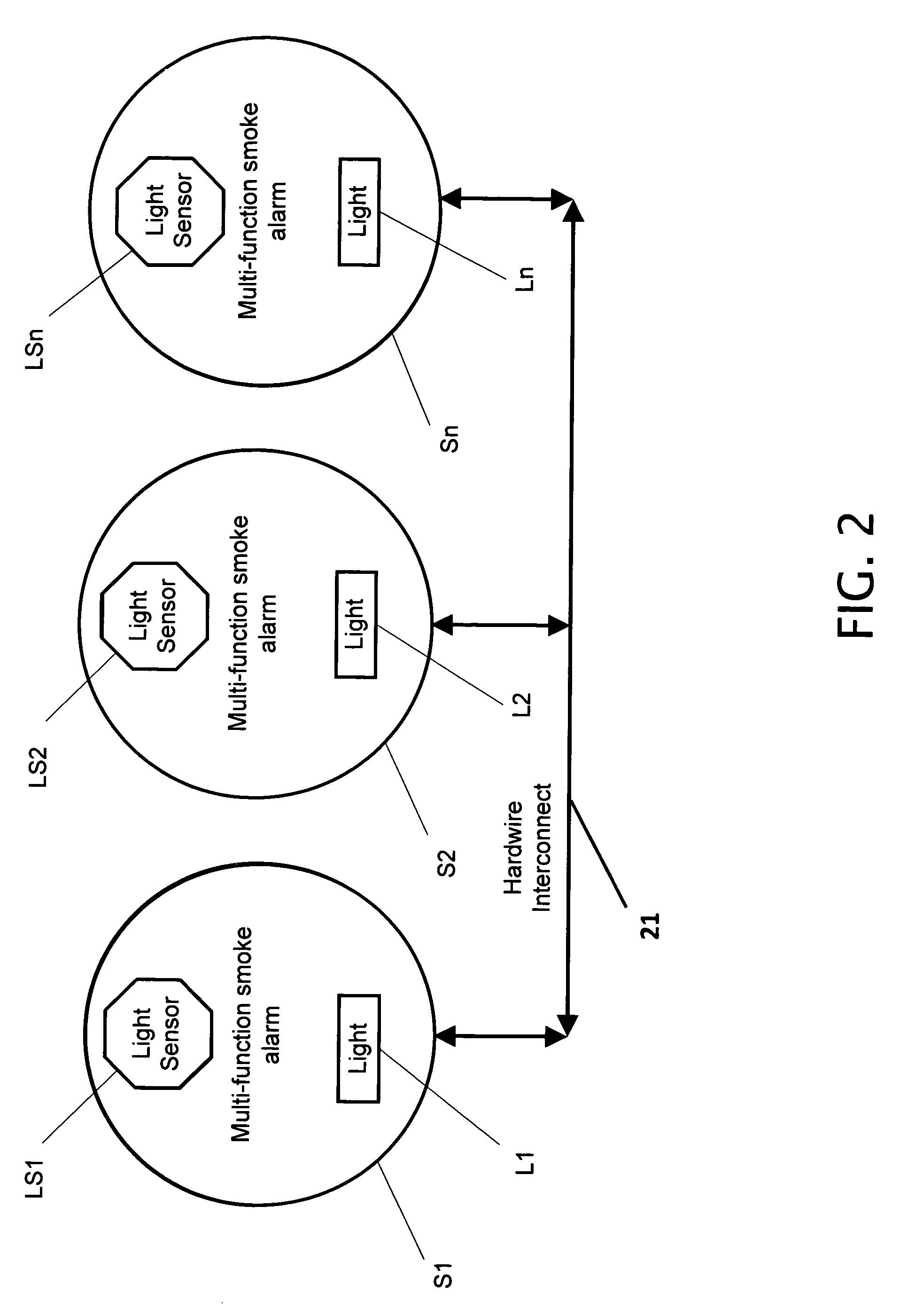
[0014]Communication can be directed to a particular unit, and the identity of a reporting unit can be determined. It can
route communication messages from any of the hardwired,
wireless, or power line interconnects to any of the other interconnect types. It can utilize the interconnect component as a means to initiate an integrity test on all the connected units. The interconnect component can be connected to a computer and used as a means to configure a unit's settings and operation and / or to download
software to a unit's
microprocessor. It can eliminate the need for separate smoke alarm systems, security systems, and occupancy-based systems of various types. A separate external controller is not required to allow use with external systems or to form a network of units. It can reduce cost, simplify installation, improve reliability, and improve appearance compared to equivalent separate single-function systems. Sensors and controls that can be operated by the multifunction smoke alarm include security systems, HVAC systems, lighting control, ceiling fans, HVAC vents, ventilation fans, motorized window coverings, and / or other systems or devices which are controlled or affected by the presence or absence of an occupant, and / or are controlled or affected by the other sensors within the unit.
[0015]It is another object of the multifunction smoke alarm unit for the unit to provide a means to control external lights for security purposes. Using the ambient light sensor, the unit can turn on external lights when the ambient light diminishes to a threshold level, and then turn them off after a predetermined
delay, simulating the presence of occupants in an otherwise empty building. When the unit is also used as an intruder alarm, this security light feature can be enabled whenever the intruder alarm is armed and otherwise disabled, thereby providing an extra degree of security. Alternatively, the security light feature can be enabled whenever the room is unoccupied and otherwise disabled.
[0016]It is another object of the multifunction smoke alarm unit for the unit to perform self testing when interconnected with other units. The multifunction smoke alarm can initiate an integrity self-test in all units from a single unit, simplifying the procedure. Alternatively, an interconnected external device such as a
control unit or computer could be used to initiate the self-test in all units and report the results. It is an industry-standard recommendation to frequently test smoke alarms for correct operation, as often as weekly. Previous smoke alarms generally provide a self-test button on the unit. In a typical home with eight smoke alarms, for example, a weekly test could be impractical, especially if some of the units are attached to a high ceiling.

