
Automatic range shift system and method for an Analog to Digital Converter

a range shift and converter technology, applied in transmission systems, physical parameter compensation/prevention, instruments, etc., can solve the problems of large portion of the span being used, large amount of unused space, etc., to achieve the effect of reducing power adcs, reducing power consumption and excess resolution

Active Publication Date: 2008-11-27
ANALOG DEVICES INC
View PDF4 Cites 10 Cited by
  • Summary
  • Abstract
  • Description
  • Claims
  • Application Information

AI Technical Summary

Benefits of technology

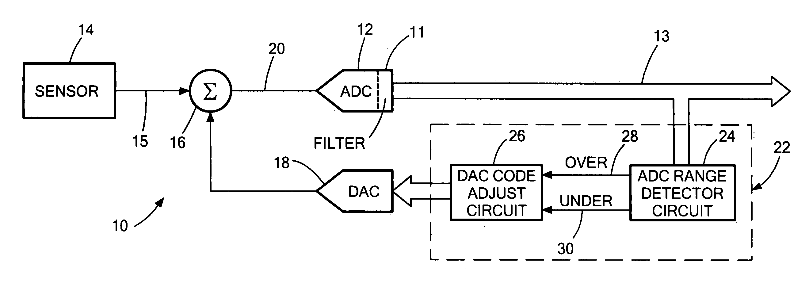
[0008]It is a further object of this invention to provide such an improved automatic range shift system and method which allows for higher resolution from coarser ADCs by shifting the ADC input signal to stay within the more limited range of a coarser ADC.
[0011]It is a further object of this invention to provide such an improved automatic range shift system and method which avoids the use of ADCs with excess resolution and more complex costly circuitry.
[0012]It is a further object of this invention to provide such an improved automatic range shift system and method which allows the DAC step to be calculated within the accuracy of the ADC.
[0013]It is a further object of this invention to provide such an improved automatic range shift system and method which allows larger input signal variations to be measured in addition to smaller short-term variations without introducing errors due to inaccuracies in the offsetting DAC.

Problems solved by technology

The complexity, size, and typically the power of an analog-to-digital converter increases with the resolution of conversion result required.
Another way of looking at the problem is that a large portion of the span is unused for most of the time.
The result is that for most of the time the converter used has excess resolution, with a more complex and costly circuit.
However, they do not automatically update the DAC in response to the ADC signal going outside range.
They do not adaptively set the DAC to keep the ADC input within range, nor do they teach this approach.
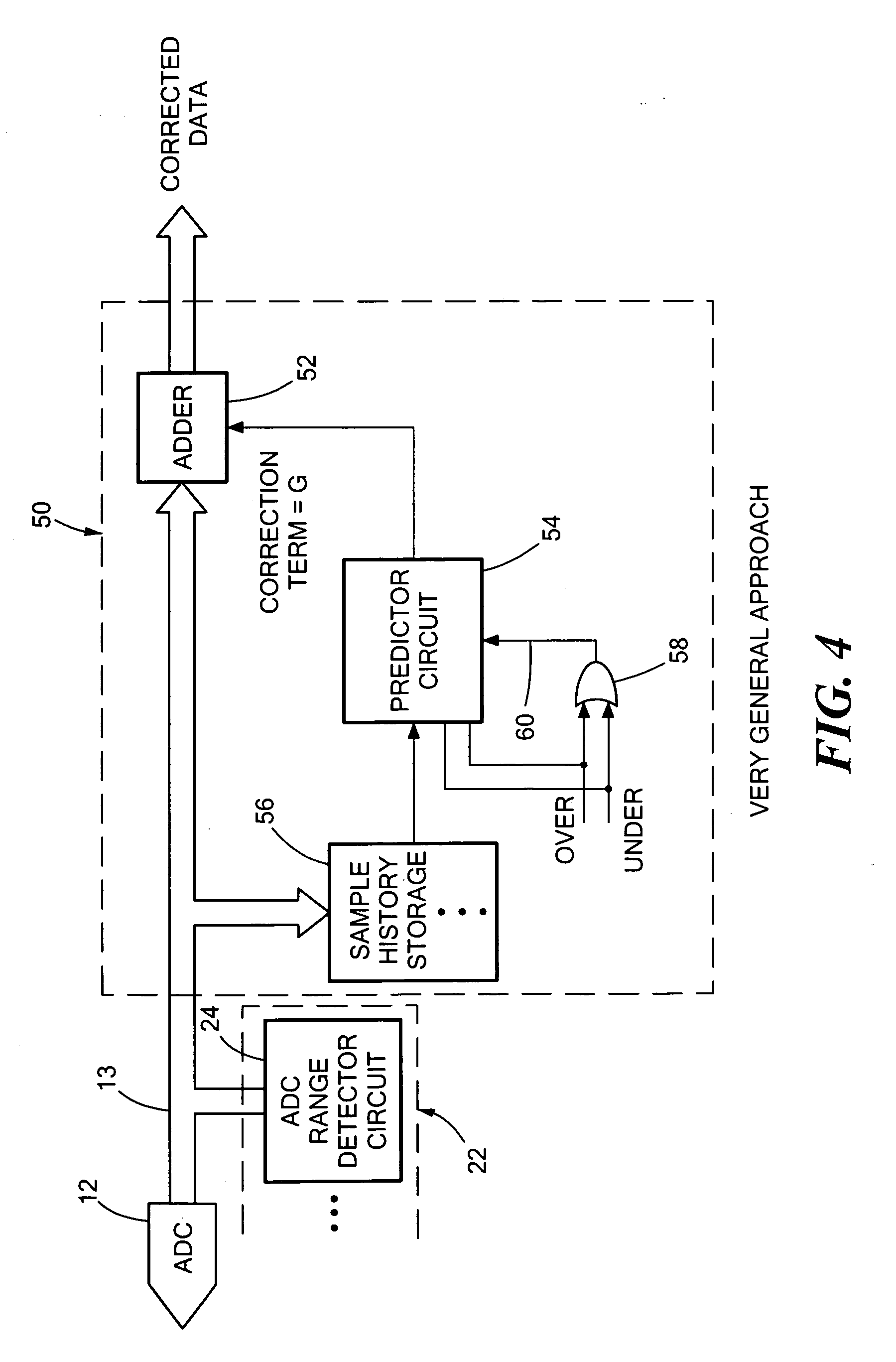
Therefore they do not teach any methods of automatic correction of the ADC output codes to take the DAC change into account.
The design of an ADC typically becomes exponentially more difficult as the number of bits N increases.
The analog circuitry in the ADC becomes larger, more complex and requires more power.
By comparison, the digital circuitry will become larger but marginally more difficult; extra digital processing is relatively easily added.
However, it is necessary to be able to adjust the location of the 0.25V sub-span across the full range; a fixed sub-span of 0 to 0.25V will not meet the objective.

Method used


Image

  • Automatic range shift system and method for an Analog to Digital Converter
  • Automatic range shift system and method for an Analog to Digital Converter
  • Automatic range shift system and method for an Analog to Digital Converter

Examples


Embodiment Construction

[0030]Aside from the preferred embodiment or embodiments disclosed below, this invention is capable of other embodiments and of being practiced or being carried out in various ways. Thus, it is to be understood that the invention is not limited in its application to the details of construction and the arrangements of components set forth in the following description or illustrated in the drawings. If only one embodiment is described herein, the claims hereof are not to be limited to that embodiment. Moreover, the claims hereof are not to be read restrictively unless there is clear and convincing evidence manifesting a certain exclusion, restriction, or disclaimer.

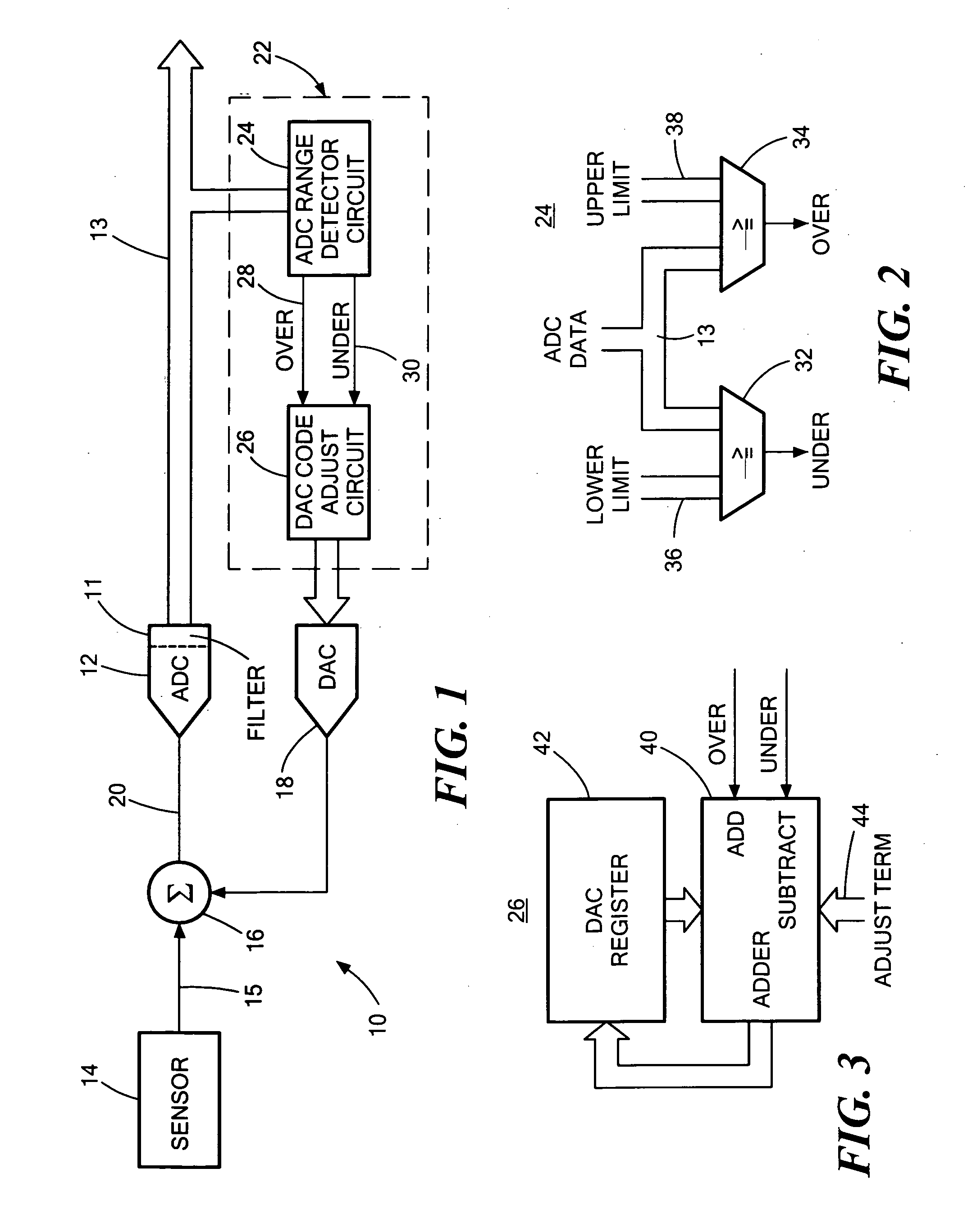
[0031]The invention uses a control circuit to automatically update the DAC to keep the signal in range by monitoring the ADC output. If the ADC output code falls below a fixed lower threshold then the DAC is decremented to increase the input signal to the ADC and pull the ADC codes towards centre scale. If the ADC output ri...


PUM


Abstract

Automatic range shifting for an analog to digital converter (ADC) includes combining an external analog input and a DAC output to provide an input to the ADC, detecting whether the range of the output of the ADC is above a predetermined upper range limit or below a predetermined lower range limit, and generating an adjustment code to increase the DAC output if the ADC output is above the upper range limit and to decrease the DAC output if the ADC output is below the lower range limit for decreasing the ADC input when the ADC output is above the upper limit and to increase the ADC input when the ADC output is below the lower limit to keep the ADC input within the ADC range.

Description

RELATED APPLICATIONS[0001]This application claims benefit of and priority to U.S. Provisional Application Ser. No. 60 / 931,447 filed May 23, 2007 incorporated herein by this reference.FIELD OF THE INVENTION[0002]This invention relates to an automatic range shift system and method for an analog to digital converter.BACKGROUND OF THE INVENTION[0003]The complexity, size, and typically the power of an analog-to-digital converter increases with the resolution of conversion result required. Typically the minimum and maximum input signals are mapped onto the span of the converter. However, in many applications the input signal may have a short-term variation which covers a subset of the converter span. The resolution required is calculated over the full span, but if you focus on the sub-span a much lower resolution is adequate. Another way of looking at the problem is that a large portion of the span is unused for most of the time. The result is that for most of the time the converter used ...

Claims


Application Information

Patent Timeline
Patent Type & Authority Applications(United States)
IPC IPC(8): H03M1/06H03M1/34
CPCH03M1/181
Inventor O'DOWD, JOHNJENNINGS, KEVINCREEDON, TADHG
Owner ANALOG DEVICES INC
Learn More