Projector and control method of projector

Active Publication Date: 2008-11-27
SEIKO EPSON CORP
View PDF2 Cites 3 Cited by
  • Summary
  • Abstract
  • Description
  • Claims
  • Application Information

AI Technical Summary

Benefits of technology

[0034]According to this control method of the projector, the light intensity control step controls the light intensity of the light projected in the projection step in the order of reception of plural operations received from the user in the operation step. In this case, the light intensity of the light projected in the projection step can be varied for each operation. Thus, the projection light having high luminance is not projected in the projection step at the start of projection but the luminance of the projection light is so controlled as to change from low to high by gradually increasing the light intensity

Problems solved by technology

However, a problem in safety that light having high luminance emitted from the projector directly enters a user's eyes is arising.
The related-art technologies shown in JP-T-11-501419 and JP-A-2004-254145 eliminate the problem when the user enters the projection area during projection of the image, but cannot cope with the case when the user already exists in the projection area before the start of image projection.
For example, when light is emitted by another person's thoughtless operation of a power source under a si

Method used


Image

  • Projector and control method of projector
  • Projector and control method of projector
  • Projector and control method of projector

Examples


Example

[0042]A projector according to a first embodiment is now described with reference to the drawings.

General Structure of Projector

[0043]Initially, the general structure of the projector according to the first embodiment is explained.

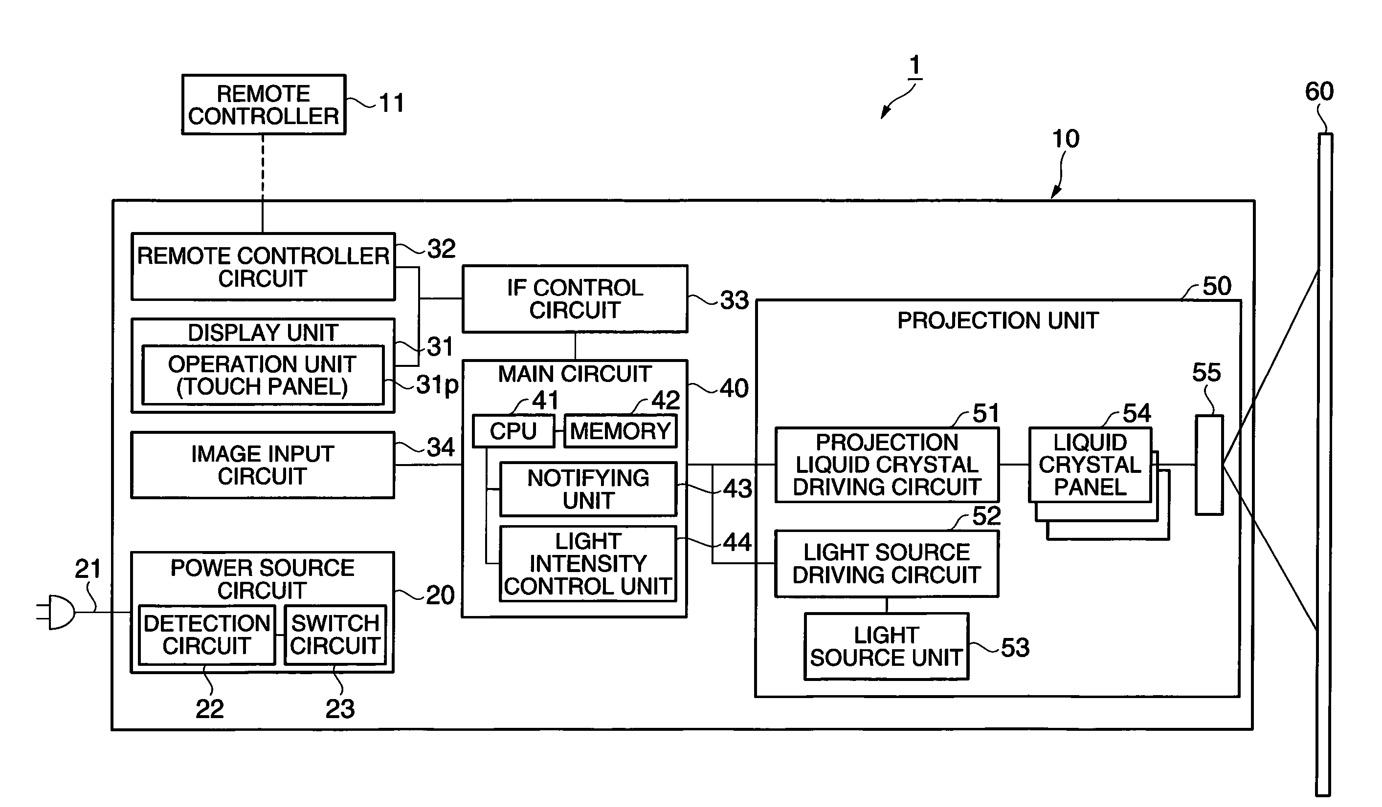
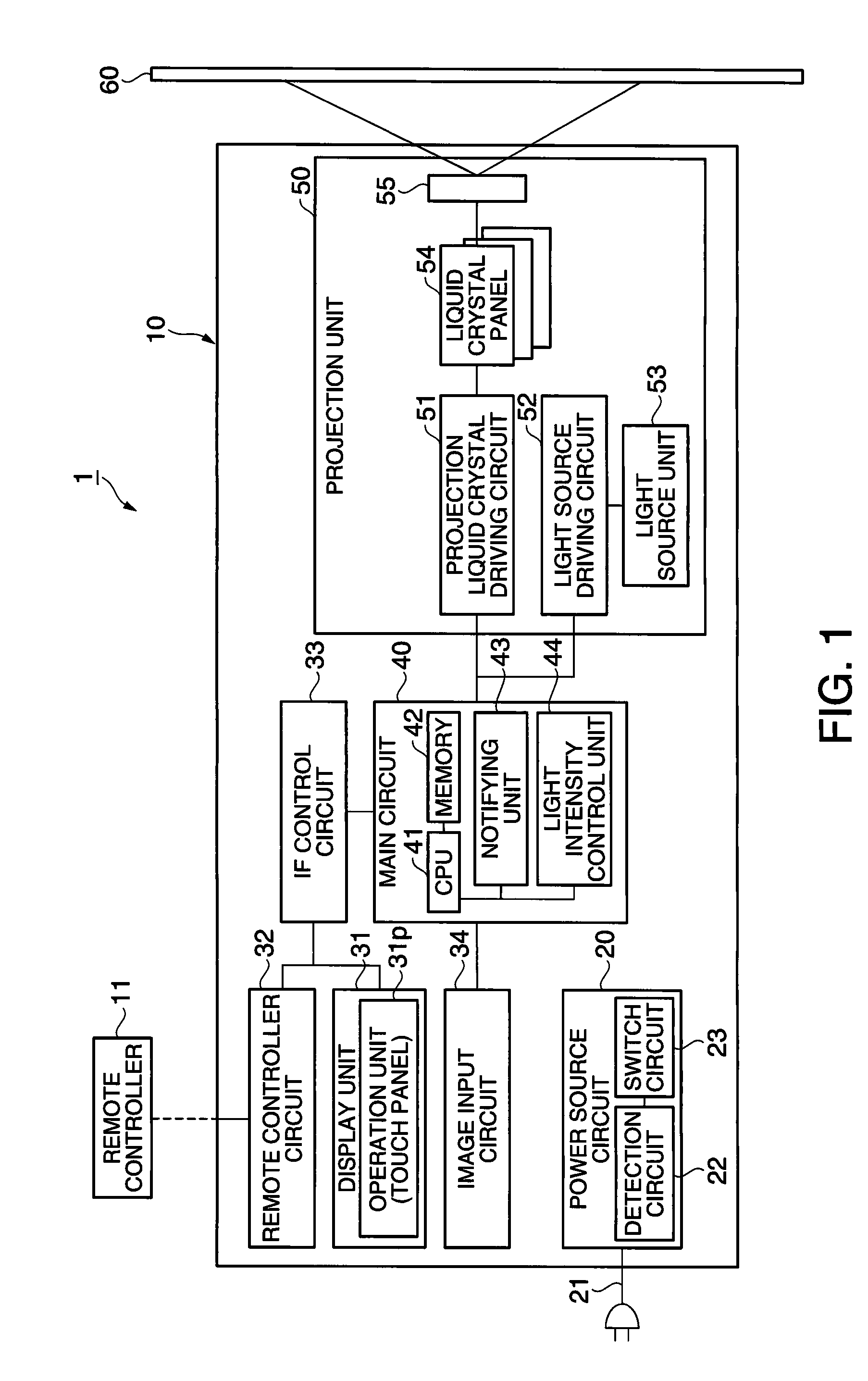
[0044]FIG. 1 is a block diagram showing the general structure of the projector according to the first embodiment. As illustrated in the figure, a projector 1 includes a projector main body 10 and a remote controller 11. The projector main body 10 contains a power source circuit 20, a display unit 31, a remote controller circuit 32, an IF (abbreviation of interface) control circuit 33, an image input circuit 34, a main circuit 40, and a projection unit 50 having a projection liquid crystal driving circuit 51, a light source driving circuit 52, a light source unit 53, liquid crystal panels 54 for respective color lights, and a projection lens 55.

[0045]The power source circuit 20 has a detection circuit 22 and a switch circuit 23. The power source circuit 20 ...

Example

Second Embodiment

[0072]A projector according to a second embodiment is now described with reference to the drawings.

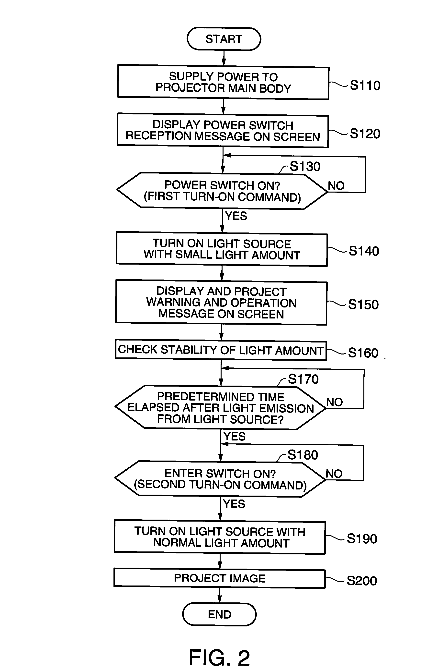
[0073]The general structure of the projector in the second embodiment is similar to that of the general structure of the projector in the first embodiment shown in FIG. 1. The operation of the projector in the second embodiment is similar to the operation shown in the flowchart in FIG. 2 according to the first embodiment, but the process for screen-displaying and projecting the warning and operation message in step S150 and the process for receiving the Enter switch in step S180 are different.

[0074]In step S150 in the second embodiment which is different from that in the first embodiment, warning and operation message shown in FIG. 5A are displayed on the screen of the touch panel 31p, for example, and warning and operation message shown in FIG. 5B are projected on the screen 60 via the projection unit 50, for example. As illustrated in FIG. 5A, the “Power” switch, and...


PUM


Abstract

A projector includes: an operation unit which receives operation by a user; a projection unit which projects light corresponding to an image signal; and a light intensity control unit which controls light intensity of the light projected by the projection unit. The light intensity control unit controls the light intensity in the order of reception of plural operations received by the operation unit from the user.

Description

BACKGROUND[0001]1. Technical Field[0002]The present invention relates to a projector and a control method of a projector.[0003]2. Related Art[0004]Recently, a projection type projector which projects light emitted from a light source on a screen has been widely used. However, a problem in safety that light having high luminance emitted from the projector directly enters a user's eyes is arising. In order to overcome this safety problem, various technologies for protecting the user's eyes from direct entrance of the light emitted from the projector are proposed. According to a projector disclosed in JP-T-11-501419, for example, a sensor detects the possibility that light emitted from the projector is applied to a human. In this case, the projector lowers power of a light source or turns off the switch of the light source. On the other hand, a projector disclosed in JP-A-2004-254145 picks up an image projected on a screen during projection of the image, and compares the obtained image...

Claims


Application Information

Patent Timeline
IPC IPC(8): G03B21/20
CPCH04N9/3155G03B21/2053G03B21/2086
Inventor NAGATE, TAKASHIYAMAUCHI, TAISUKE
Owner SEIKO EPSON CORP
Why Eureka
Try Eureka