Phase difference compensating device and liquid crystal apparatus using the same

a phase difference and compensating device technology, applied in non-linear optics, instruments, optics, etc., can solve the problems of inability to avoid the dependence of a modulation degree on the angle, narrow field of view, and low extent of dark state of tn liquid crystal display devices, etc., to achieve high heat resistance, high physical stability, and high contrast of displayed images

Inactive Publication Date: 2006-05-04
FUJIFILM CORP +1
View PDF9 Cites 8 Cited by
  • Summary
  • Abstract
  • Description
  • Claims
  • Application Information

AI Technical Summary

Benefits of technology

[0046] With the phase difference compensating device in accordance with the present invention, each of the two second phase difference compensating layers, which are adapted to compensate for the phase difference occurring due to the birefringence by the liquid crystal molecules having undergone the hybrid orientation in the liquid crystal layer, is constituted of one of the two oblique incidence vacuum deposited films, which are formed such that at least either one of the azimuthal angle of the direction of vacuum evaporation with respect to the plane of vacuum evaporation of the oblique incidence vacuum deposited film and the polar angle of the direction of vacuum evaporation with respect to the plane of vacuum evaporation of the oblique incidence vacuum deposited film is set to be different between the two second phase difference compensating layers having been formed on the opposite surfaces of the base plate. Therefore, good effects of phase difference compensation are capable of being obtained. Accordingly, for example, in cases where the phase difference compensating device in accordance with the present invention is utilized in combination with a TN liquid crystal display device operating in the normally white mode, the occurrence of light leakage during the dark state displaying is capable of being suppressed with respect to the oblique incident light. As a result, the contrast of the displayed image is capable of being kept high.
[0047] Also, with the phase difference compensating device in accordance with the present invention, the second phase difference compensating layers, each of which is constituted of the inorganic material, have a high heat resistance and a highlight resistance. Further, the second phase difference compensating layers have a high physical stability and a high chemical stability. Therefore, the phase difference compensating device in accordance with the present invention has the advantages in that the phase difference compensating device is capable of being applied to the liquid crystal projectors, in which a high luminance light source is utilized. Furthermore, with the phase difference compensating device in accordance with the present invention, the first phase difference compensating layer is capable of being constituted of the vacuum deposited films of the inorganic materials. Therefore, the first phase difference compensating layer and the second phase difference compensating layers are capable of being formed efficiently with serial processes.
[0048] Further, with the phase difference compensating device in accordance with the present invention, each of the two second phase difference compensating layers is constituted of one of the two oblique incidence vacuum deposited films, each of which is formed on one of the opposite surfaces of the base plate. Therefore, the problems, which are apt to occur in cases where a plurality of oblique incidence vacuum deposited films are laminated together on one surface of the base plate, are capable of being eliminated. Specifically, it is possible to prevent the problems from occurring in that, in cases where an oblique incidence vacuum deposited film is overlaid upon an underlying oblique incidence vacuum deposited film, which varies in azimuthal angle or a polar angle of the direction of vacuum evaporation from the overlaid oblique incidence vacuum deposited film, an uneven surface state of the underlying oblique incidence vacuum deposited film is reflected upon the overlaid oblique incidence vacuum deposited film, cloudiness thus occurs with the film, and the optical performance becomes bad. Also, it is possible to prevent the problems from occurring in that, though the cloudiness does not occur with the film, the reproducibility of the phase difference compensating layers is not capable of being kept high.

Problems solved by technology

Ordinarily, the TN liquid crystal display device has the drawbacks in that the field of view is narrow.
The aforesaid drawbacks of the TN liquid crystal display device arise since the liquid crystal molecules act also as birefringent media.
As a result, the extent of the dark state of the TN liquid crystal display device becomes low.
Therefore, in the state in which a continuous tone image is displayed, in cases where the display screen is seen from an oblique direction, dependence of a modulation degree upon the angle is not capable of being avoided.
Also, in cases where the TN liquid crystal display device is employed as the image display device of the liquid crystal projector, the aforesaid field angle characteristics of the TN liquid crystal display device cause a phenomenon to occur in that the contrast of the image projected onto a screen becomes low.
In both the cases described above, the aforesaid field angle characteristics of the TN liquid crystal display device cause the image quality of the displayed image to become markedly low.
With the birefringent material described in Japanese Unexamined Patent Publication No. 2004-102200, the phase difference compensation is not perfect with respect to the birefringence due to the liquid crystal molecules, which are located in the region close to the base plate.

Method used


Image

  • Phase difference compensating device and liquid crystal apparatus using the same
  • Phase difference compensating device and liquid crystal apparatus using the same
  • Phase difference compensating device and liquid crystal apparatus using the same

Examples


first embodiment

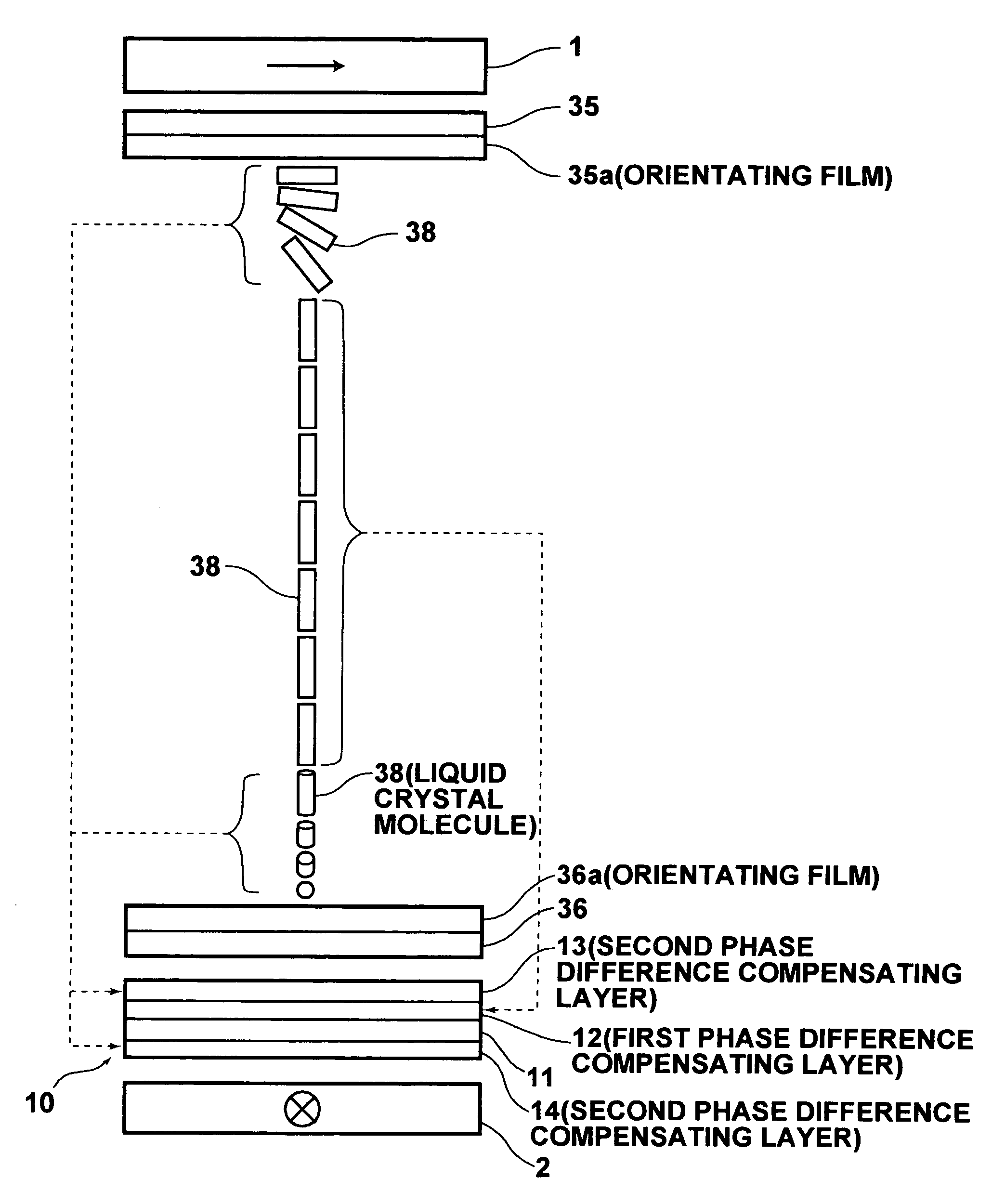
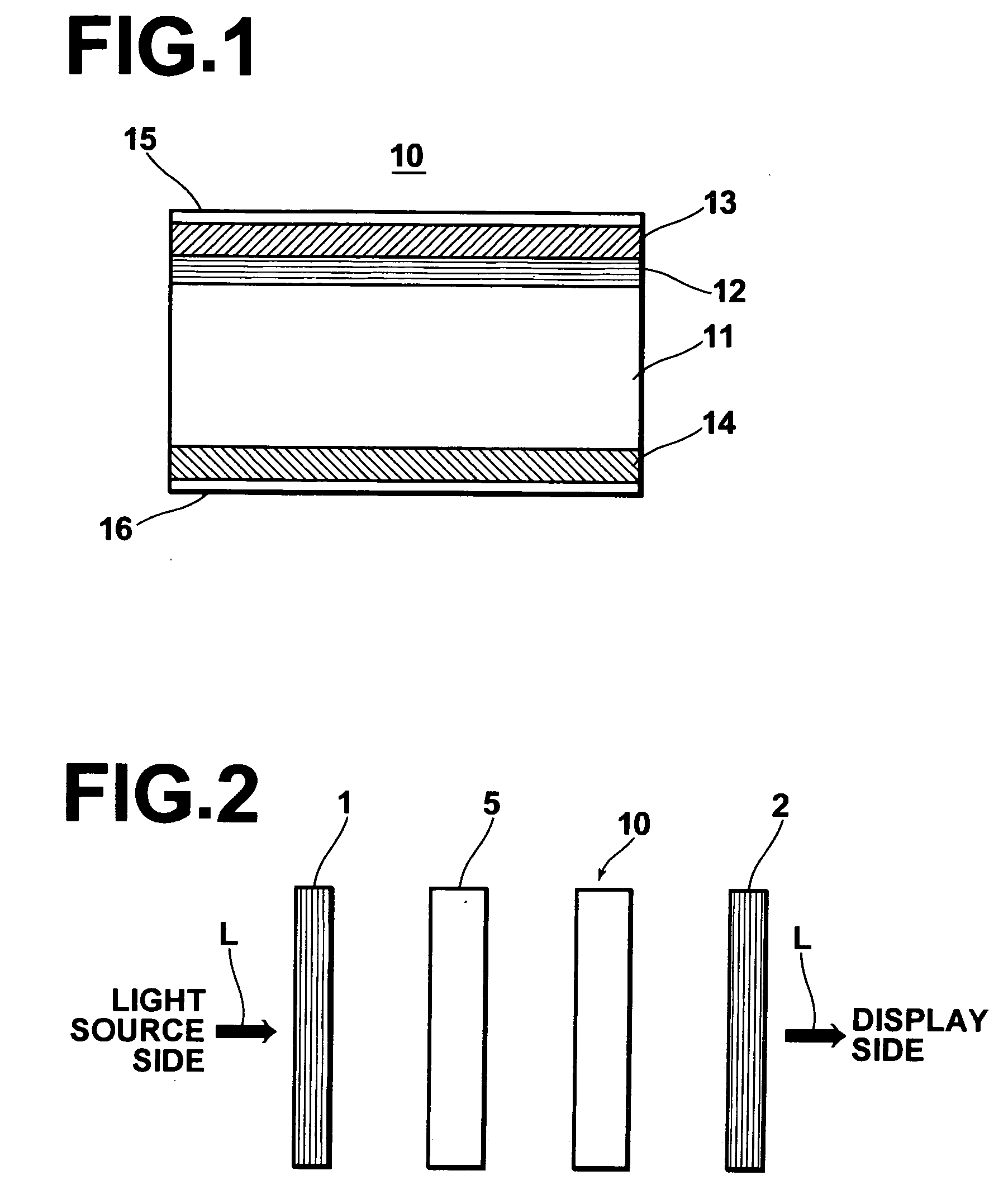
[0064]FIG. 1 is a schematic sectional side view showing a phase difference compensating device 10, which is a first embodiment of the phase difference compensating device in accordance with the present invention. FIG. 2 is a schematic view showing an example of a displaying system, in which the phase difference compensating device 10 in accordance with the present invention is employed. Firstly, the phase difference compensating device 10 will be described hereinbelow with reference to FIG. 1. As illustrated in FIG. 1, the phase difference compensating device 10 comprises a transparent base plate 11, which may be made from glass, or the like. The phase difference compensating device 10 also comprises a first phase difference compensating layer 12, which is formed on one surface of the transparent base plate 11 (i.e., the top surface of the transparent base plate 11 in FIG. 1). The phase difference compensating device 10 further comprises a second phase difference compensating layer ...

second embodiment

[0092] A second embodiment of the phase difference compensating device in accordance with the present invention will be described hereinbelow with reference to FIG. 5. FIG. 5 is a schematic sectional side view showing a phase difference compensating device 40, which is a second embodiment of the phase difference compensating device in accordance with the present invention. As illustrated in FIG. 5, the phase difference compensating device 40 comprises a transparent base plate 41, which is provided with phase difference compensating layers formed on opposite surfaces, and a transparent base plate 44, which is provided with phase difference compensating layers formed on opposite surfaces. Specifically, a second phase difference compensating layer 42 is formed on one of the opposite surfaces of the transparent base plate 41, and a second phase difference compensating layer 43 is formed on the other surface of the transparent base plate 41. Also, a second phase difference compensating l...


PUM

PropertyMeasurementUnit
angleaaaaaaaaaa
thicknessaaaaaaaaaa
sizeaaaaaaaaaa

Abstract

A transparent base plate supports a first compensating layer, which is adapted to compensate for a phase difference due to liquid crystal molecules having undergone normal orientation in a liquid crystal layer of a TN liquid crystal display device, and second compensating layers, which are adapted to compensate for the phase difference due to the liquid crystal molecules having undergone hybrid orientation in the liquid crystal layer. Each of the second compensating layers is constituted of one of oblique incidence vacuum deposited films, which are formed on opposite surfaces of the base plate with oblique incidence vacuum evaporation of an inorganic material. An azimuthal angle and/or a polar angle of a direction of vacuum evaporation with respect to a plane of vacuum evaporation is set to be different between the second compensating layers.

Description

BACKGROUND OF THE INVENTION [0001] 1. Field of the Invention [0002] This invention relates to a phase difference compensating device for eliminating the problems from occurring in that, in cases where an image displayed on an image display device utilizing a twisted nematic liquid crystal (hereinbelow referred to as the TN liquid crystal) is seen, image contrast becomes low in accordance with an field of view. This invention also relates to a liquid crystal apparatus, such as a liquid crystal projector, using the phase difference compensating device. [0003] 2. Description of the Related Art [0004] Liquid crystal display devices operating in various different operation modes have heretofore been known. In particular, for the advantages with regard to mass production, the TN liquid crystal display devices have become popular as image display devices of direct viewing types of flat panel display apparatuses and liquid crystal projectors. The TN liquid crystal display devices comprise a...

Claims


Application Information

Patent Timeline
Patent Type & Authority Applications(United States)
IPC IPC(8): G02F1/1335
CPCG02F1/133632G02F1/133634G02F1/1396
Inventor FUJII, TAKAMICHINAKAGAWA, KENICHI
Owner FUJIFILM CORP
Why Eureka
Try Eureka