Fuel Cell Flow Field Channel with Partially Closed End

a fuel cell and flow field technology, applied in the field of fuel cells, can solve the problems of consuming some of the electrical energy generated by the fuel cell, forcing the convection of the reactant gas toward, and relatively greater exposure of the reactant gas to the catalys

Active Publication Date: 2008-11-27
AUDI AG
View PDF24 Cites 38 Cited by
  • Summary
  • Abstract
  • Description
  • Claims
  • Application Information

AI Technical Summary

Problems solved by technology

This results in forced convection of the reactant gas toward the catalyst and relatively greater exposure of reactant gas to the catalyst.
The forced convection, however, increases a pressure drop of the reactant gases across the flow field and therefore requires a higher pressurization of the reactant gas

Method used


Image

  • Fuel Cell Flow Field Channel with Partially Closed End
  • Fuel Cell Flow Field Channel with Partially Closed End
  • Fuel Cell Flow Field Channel with Partially Closed End

Examples


Embodiment Construction

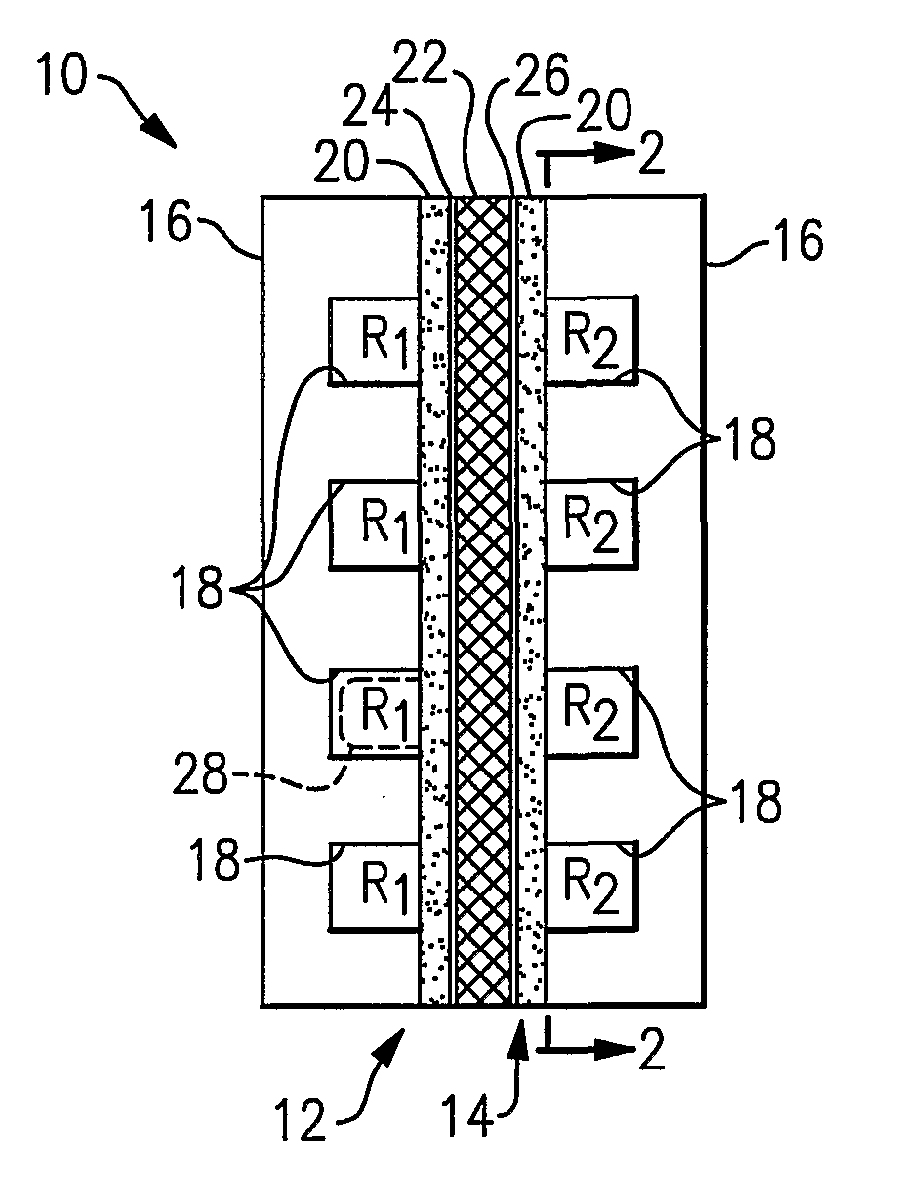
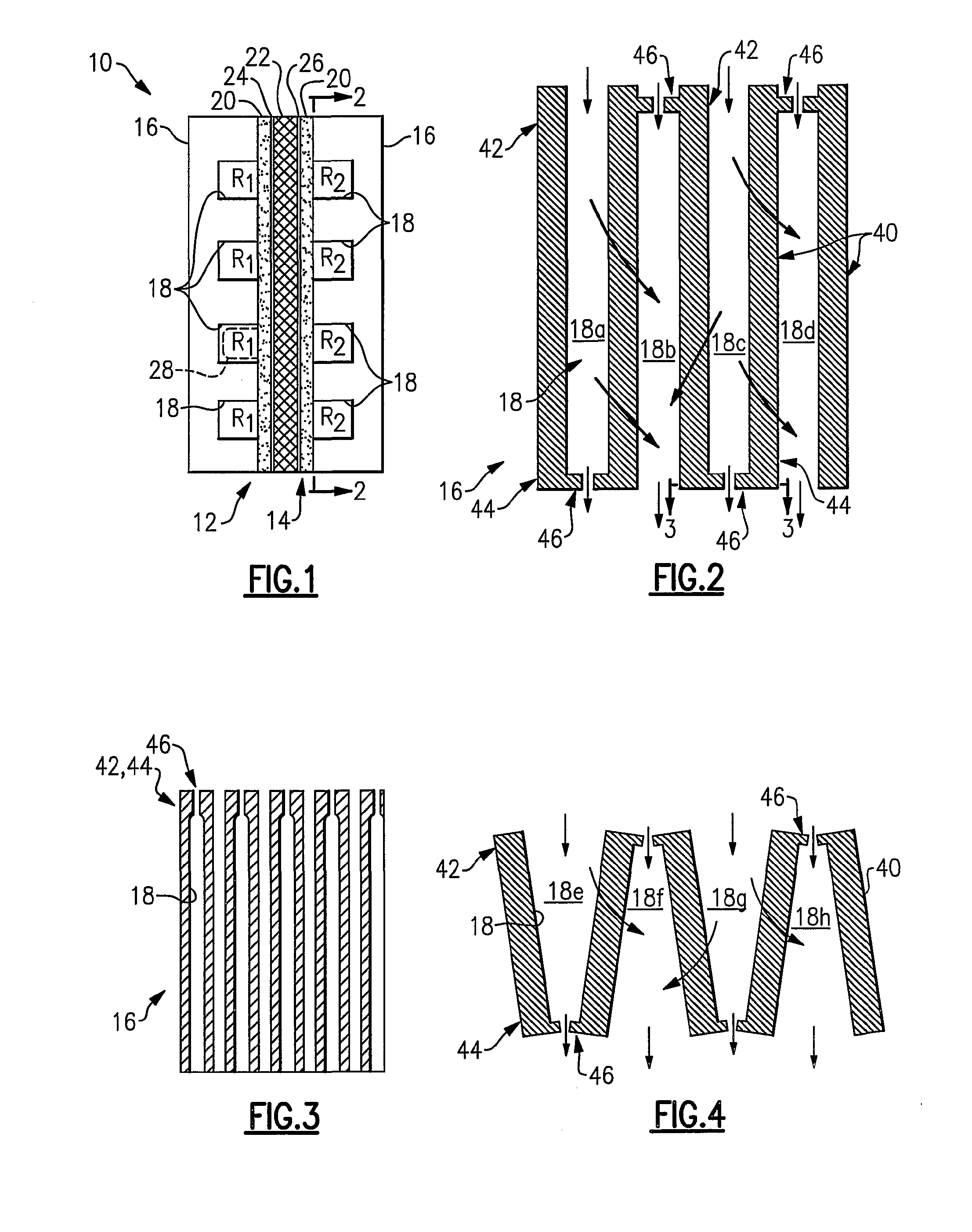
[0020]FIG. 1 schematically illustrates selected portions of an example fuel cell stack 10 for generating electricity. In this example, an anode side 12 receives a reactant gas R1 and a cathode side 14 receives a reactant gas R2 to generate an electric current in a known manner. Each of the anode side 12 and the cathode side 14 includes a flow field plate 16, such as a machined plate, molded plate, stamped plate, solid plate, porous plate, or other type of plate, having channels 18 for distributing the reactant gasses R1 and R2 over the respective anode side 12 and cathode side 14.

[0021]In the illustrated example, a gas exchange layer 20 is located adjacent each of the flow field plates 16. An electrolyte layer 22 spaces an anode catalyst 24 from a cathode catalyst 26 between the gas exchange layers 20.

[0022]In the illustrated example, the channels 18 have a rectangular cross-sectional profile. In another example, the channels 18 have a curved profile, such as that shown in phantom a...


PUM


Abstract

A device (10) for use in a fuel cell includes a fuel-cell flow-field channel (18) having a channel-inlet section (42) and a channel-outlet section (44). At least one of the channel-inlet section (42) or the channel-outlet section (44) includes an obstruction member (46) that partially blocks flow through the fuel-cell flow-field channel (18).

Description

FIELD OF THE INVENTION[0001]This invention generally relates to fuel cells and, more particularly, to flow fields for fuel cells.DESCRIPTION OF THE RELATED ART[0002]Fuel cells are widely known and used for generating electricity in a variety of applications. A typical fuel cell utilizes reactant gases, such as hydrogen or natural gas and oxygen, to generate an electrical current. Typically, the fuel cell includes adjacent flow fields that each receives a reactant gas. Each flow field distributes the reactant gas through a gas distribution layer to a respective anode catalyst or a cathode catalyst adjacent an electrolyte layer to generate the electrical current. The electrolyte layer can be any layer that effectively transports ions, but does not conduct ions. Some example fuel-cell electrolytes include: alkaline solutions (e.g., KOH), proton-exchange membranes (PEM), phosphoric acid, and solid oxides.[0003]One type of flow field includes entrance channels interdigitated with exit ch...

Claims


Application Information

Patent Timeline
IPC IPC(8): H01M8/02
CPCH01M8/0258H01M8/04089Y02T90/32H01M2250/20Y02E60/50H01M8/04223H01M8/0265H01M8/04225H01M8/04228H01M8/04302H01M8/04303Y02T90/40H01M8/02H01M8/0263
Inventor PERRY, MICHAEL L.CIPOLLINI, NED EMIDIO
Owner AUDI AG
Why Eureka
Try Eureka