
Wireless mesh point portable data terminal

a portable data terminal and wireless technology, applied in the field of data collection systems employing portable data terminals, can solve the problems of dead zones, metal structures and water obstructing the free propagation of radio waves, and the disconnectivity of such systems remains

Active Publication Date: 2008-11-27
HAND HELD PRODS
View PDF47 Cites 42 Cited by
  • Summary
  • Abstract
  • Description
  • Claims
  • Application Information

AI Technical Summary

Benefits of technology

[0012]A portable data terminal (PDT) adapted to participate in a wireless mesh network including a plurality of peer PDTs can comprise: a PDT module including an encoded information reading (EIR) device, and a mesh point (MP) module communicatively coupled to the PDT module. The MP module can include a microcontroller and at least one wireless communication interface and can be configured to perform IEEE 802.11-conformant wireless station services including authentication, de-authentication, privacy, and MAC service data unit delivery, and IEEE 802.11-conformant wireless distribution system services including association, disassociation, distribution, integration, and re-association.

Problems solved by technology

For example, while wireless data collection systems have proliferated, connectivity issues remain with such systems.
In deploying a wireless data collection system, a costly “site survey” is often commissioned to search for “dead zones” in work environments.
Dead zones are prevalent in many data collection work environments, particularly where obstructions to free radio wave propagation exist.
Metal structures and water are known to obstruct the free propagation of radio waves.
The additional access points are costly and typically require connection to an expanded wireline bus.

Method used


Image

  • Wireless mesh point portable data terminal
  • Wireless mesh point portable data terminal
  • Wireless mesh point portable data terminal

Examples


Embodiment Construction

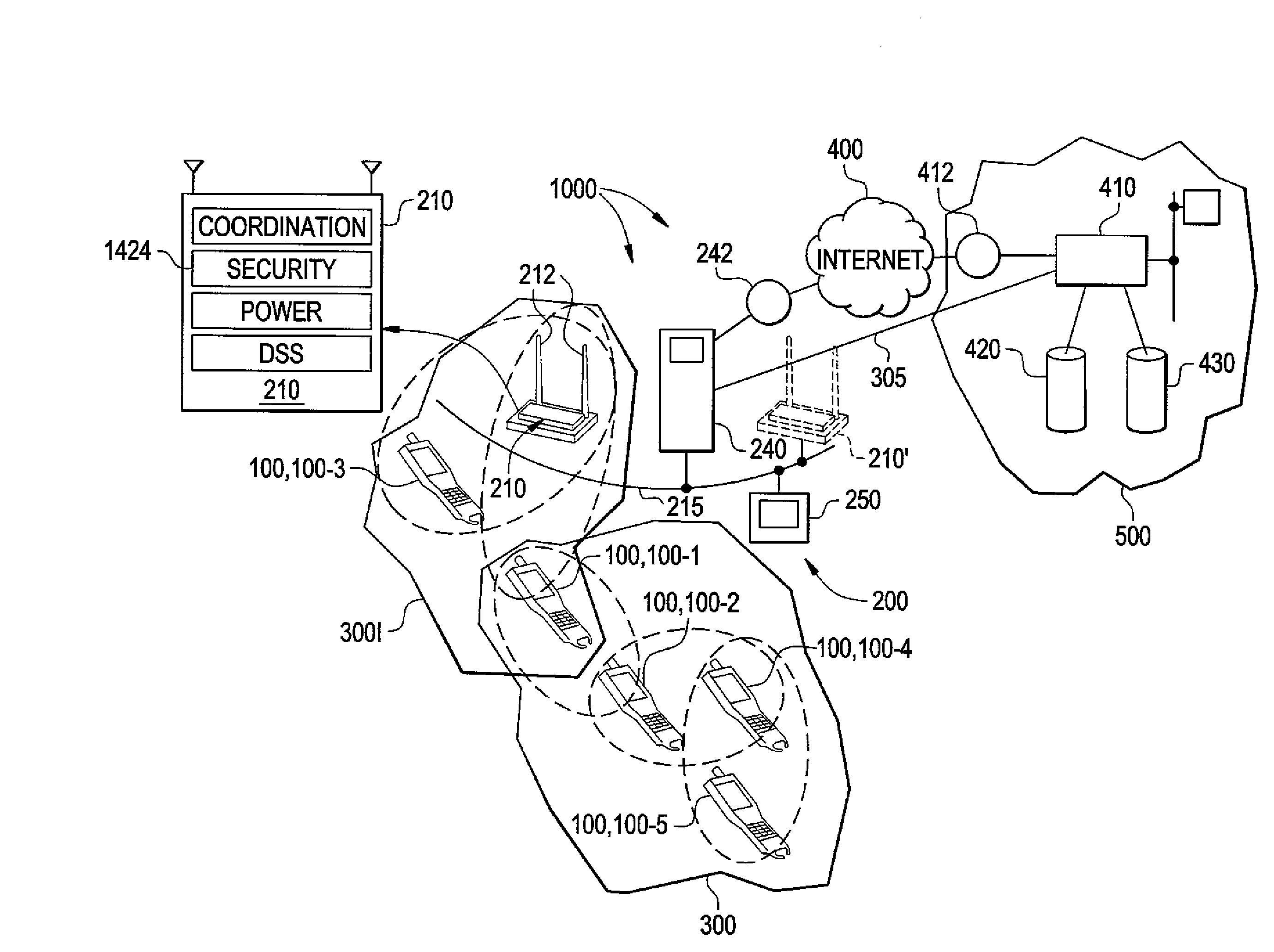
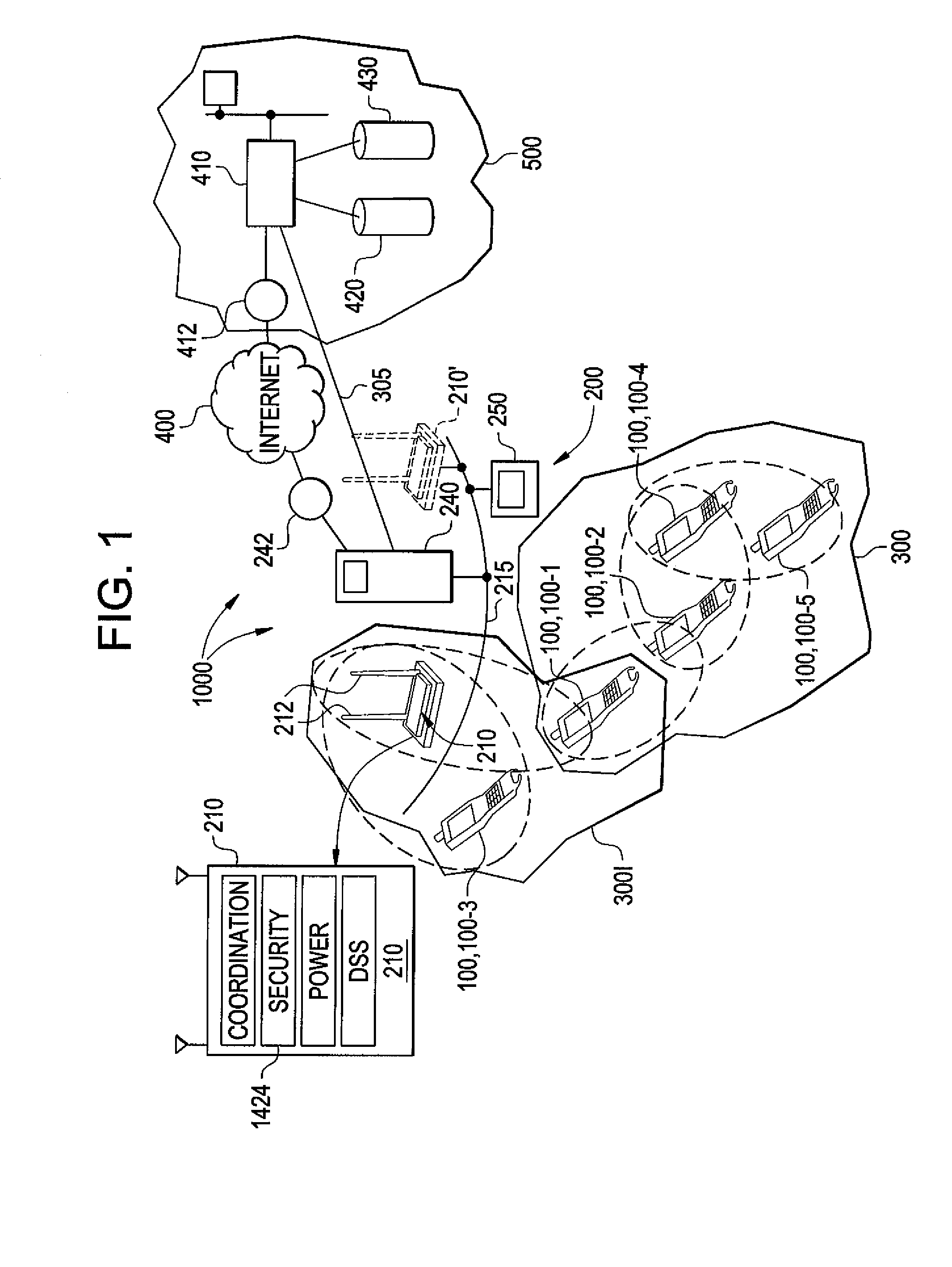
[0028]There is provided a data collection system comprising a plurality of PDTs as shown in FIG. 1. A PDT can be provided, for example, by a bar code scanner, a personal data assistant (PDA), or a cellular telephone. A skilled artisan would appreciate the fact that other portable computing devices are within the scope and the spirit of the invention. The data collection system according to the invention can include more than one such type or category of PDT.

[0029]As shown in FIG. 1, the data collection system 1000 can include a plurality of networks 200, 3001, 300, 400, and 500. Network 200 is a wireline local area network (LAN), networks 300 and 3001 are IEEE 802.11-compliant wireless networks, network 400 is an IP network shown in the specific embodiment as the Internet, and network 500 is a remote data archiving network managed by a data archiving entity. The data collection system 1000 can include a plurality of PDTs 100-1, 100-2, 100-3, 100-4, 100-5 and an access point (AP) 210...


PUM


Abstract

A portable data terminal (PDT) adapted to participate in a wireless mesh network including a plurality of peer PDTs can comprise: a PDT module including an encoded information reading (EIR) device, and a mesh point (MP) module communicatively coupled to the PDT module. The MP module can include a microcontroller and at least one wireless communication interface and can be configured to perform IEEE 802.11-conformant wireless station services including authentication, de-authentication, privacy, and MAC service data unit delivery, and IEEE 802.11-conformant wireless distribution system services including association, disassociation, distribution, integration, and re-association. The MP module can be further configured, responsive to receiving a MAC frame addressed to a recipient inside the wireless mesh network, to deliver the MAC frame using the distribution service. The MP module can be further configured, responsive to receiving a MAC frame addressed to a recipient outside of the wireless mesh network, to deliver the MAC frame using the integration service. The MP module can be further configured to route an incoming MAC frame according to its destination address and the frame control field. The MP module can be further configured to cause the PDT module to exit said sleeping state responsive to receiving a mobile management software (MMS) wake-up command.

Description

CROSS REFERENCE TO RELATED APPLICATIONS[0001]This application claims priority under 35 U.S.C. § 119(e) of the following provisional application: U.S. Ser. No. 60 / 931,850, filed May 25, 2007, entitled “Wireless Mesh Point Data Collection Device Terminal”, the content of which is incorporated herein by reference.FIELD OF THE INVENTION[0002]The invention is generally related to data collection systems employing portable data terminals and is specifically related to a system and method of wireless data communication in a data collection system employing portable data terminals.BACKGROUND OF THE INVENTION[0003]In recent years significant advances have been made in the art of data collection devices and networks containing the same.[0004]In U.S. Pat. No. 5,900,613, a data collection device system is described having a data collection device adapted to read bar code data wherein the data collection device is in communication with a local host processor and a remote host processor. The data...

Claims


Application Information

Patent Timeline
IPC IPC(8): G06F15/173G06F1/28
CPCH04W16/26H04W52/0203H04W84/22H04W24/02H04W52/0209Y02D30/70H04B1/38H04W84/18
Inventor WANG, YNJIUN P.HAVENS, WILLIAM H.QU, HUYU
Owner HAND HELD PRODS
Learn More