Deploy target computer, deployment system and deploying method

Inactive Publication Date: 2008-11-27
HITACHI LTD
View PDF1 Cites 56 Cited by
  • Summary
  • Abstract
  • Description
  • Claims
  • Application Information

AI Technical Summary

Benefits of technology

[0012]According to the present invention, the deploy target server can be brought into the state where the boot can b

Problems solved by technology

Even if a fast communication network is used to copy the OS image, however, some time is required to conduct the copying and consequently it takes some ti

Method used


Image

  • Deploy target computer, deployment system and deploying method
  • Deploy target computer, deployment system and deploying method
  • Deploy target computer, deployment system and deploying method

Examples


first embodiment

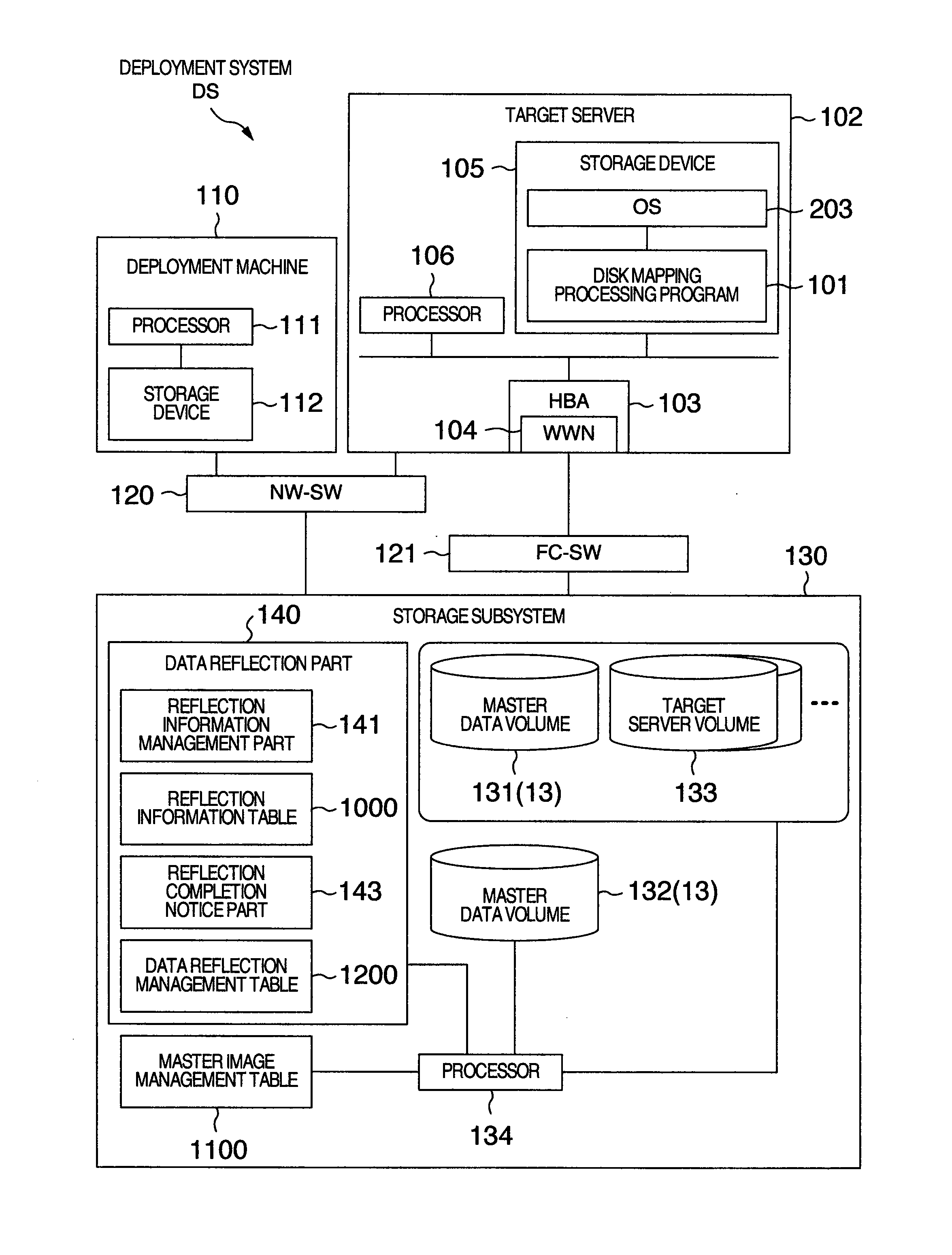
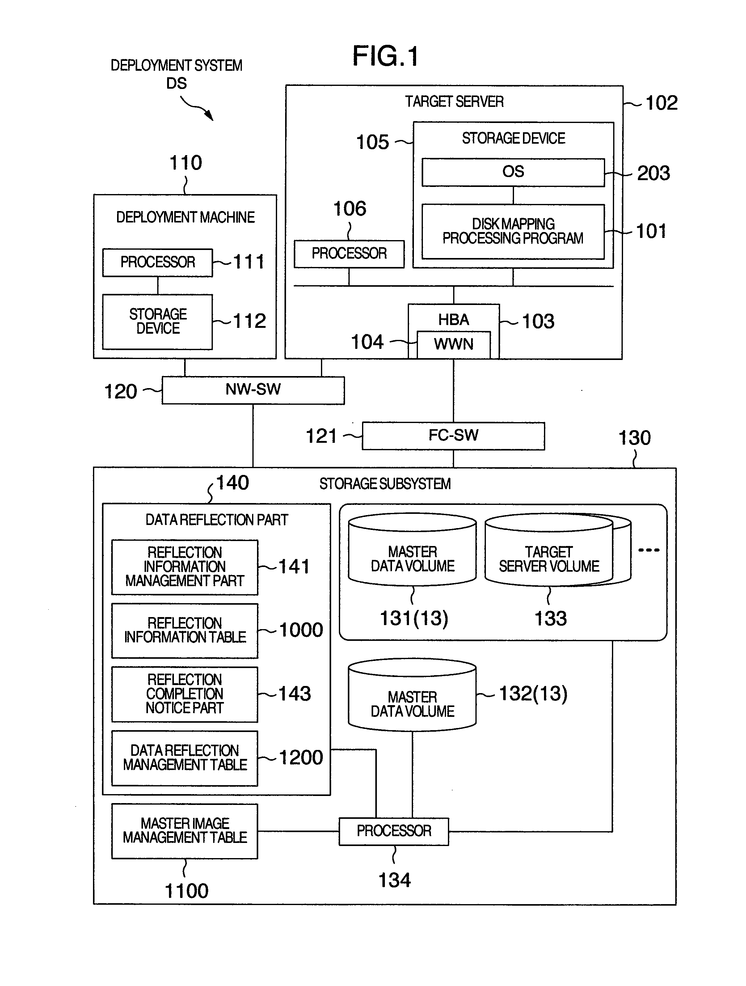
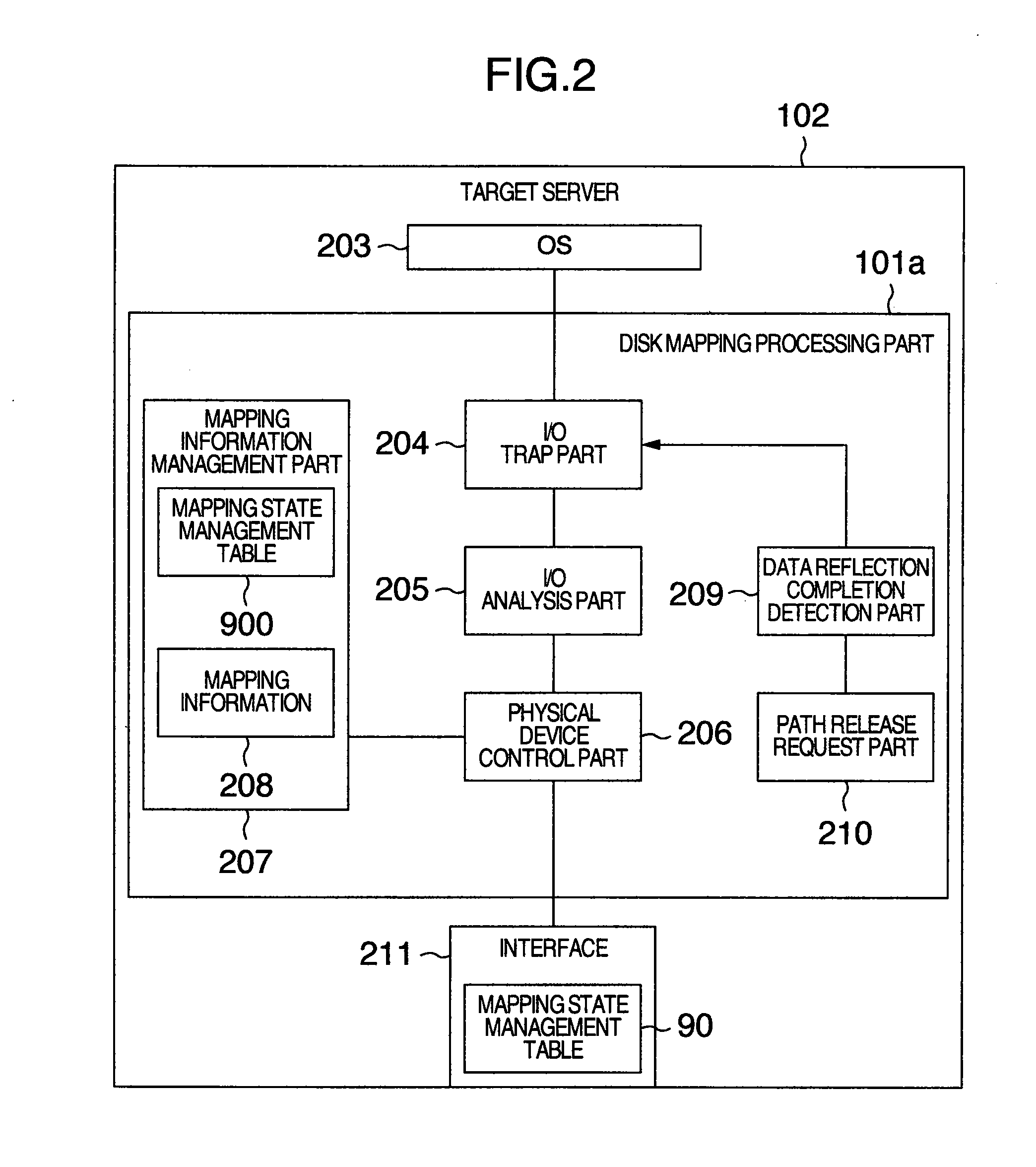
[0030]FIG. 1 is a general configuration diagram of a deployment system according to a first embodiment of the present invention. In a deployment system DS, a deploy target server 102 (deploy target computer) including a disk mapping processing program 101 includes an HBA (Host Bus Adapter) 103 for conducting fiber channel communication. The deploy target server 102 is connected to a storage subsystem 130 (storage device) storing an OS (Operating System) image to be deployed via a FC-SW (Fiber Channel Switch) 121. Furthermore, a deployment machine 110 for issuing a deploy instruction, the target server 102, and the storage subsystem 130 are connected via a NW-SW (NetWork Switch) 120. In the target server 102, a processor 106 and the disk mapping processing program 101 are collectively referred to as disk mapping processing part 101a (which will be described with reference to FIG. 2 later).

[0031]The OS image is one form of the boot disk image (which is a general term of images require...

second embodiment

[0084]FIG. 15 is a general configuration diagram of a deployment system according to a second embodiment of the present invention. In a deployment system DSa shown in FIG. 15, a plurality of logical sections 1301, 1302 and 1303 (hereafter referred to as “logical section 13000” unless especially distinguished) are generated by logically dividing physical computer resources included in one physical computer 1300. In this example, the disk mapping processing part 101a is provided in a control program (hypervisor 1304 (VMM: Virtual Machine Monitor)) which controls the logical section 13000 in a logical computer system (not illustrated) capable of simultaneously executing at least one OS (first guest OS to third guest OS (hereafter referred to as “guest OS” unless especially distinguished)).

[0085]If the disk mapping processing part 101a is thus provided in the virtualization mechanism, then it becomes unnecessary to provide the disk mapping processing part 101a in the logical section 130...


PUM


Abstract

A deploy target computer is connected to a storage device including a replication source logical disk used to store a boot disk image. A disk mapping processing part in the deploy target computer changes over access destination so as to set the access destination to the replication source logical disk in the storage device when an I/O request is issued from the deploy target computer to the storage device and the I/O request specifies reading the boot disk image, and so as to set the access destination to a replication destination logical disk for conducting writing concerning the boot disk image when the I/O request specifies writing concerning the boot disk image.

Description

INCORPORATION BY REFERENCE[0001]The present application claims priority from Japanese application JP2007-133825 filed on May 21, 2007, the content of which is hereby incorporated by reference into this application.BACKGROUND OF THE INVENTION[0002]1. Field of the Invention[0003]The present invention relates to a technique for deploying a boot (start) disk image in a computer (deploy target computer) such as a server.[0004]2. Description of the Related Art[0005]In recent years, flexible server construction according to a business load is demanded in operation of a system including a large number of servers. In other words, specifically, shortening of the server construction time is first demanded. For the server construction, it becomes necessary to deploy a boot disk image in a server. Here, the boot disk image refers to an image obtained when a program required for the server to boot is installed in a storage area. Hereafter, however, it is represented by “OS (Operating System) imag...

Claims


Application Information

Patent Timeline
IPC IPC(8): G06F9/00
CPCG06F8/63G06F9/45533
Inventor ANDO, MASAHIKOKATO, AKIRAGOTO, SUMIO
Owner HITACHI LTD
Why Eureka
Try Eureka